Inst ToolsInst ToolsInst Tools
  • Ask
  • Courses
  • Videos
  • Q & A
    • Interview
      • Instrumentation
      • Electronics
      • Electrical
      • Practical Questions
    • MCQ
      • Instrumentation MCQ
      • Electrical MCQ
      • Electronics MCQ
      • Control Systems MCQ
      • Analog Electronics MCQ
      • Digital Electronics MCQ
      • Power Electronics MCQ
      • Microprocessor MCQ
      • Multiple Choice Questions
  • EE
    • Electronics
      • Electronics Q & A
      • Electronic Basics
      • Electronic Devices & Circuits
      • Electronics Animation
      • Digital Electronics
    • Electrical
      • Electrical Basics
      • Electrical Q & A
      • Power Electronics
      • Electrical Machines
      • Electrical Animation
      • Power Systems
      • Switchgear & Protection
      • Transmission & Distribution
  • Measure
    • Control Valves
    • Calibration
    • Temperature
    • Pressure
    • Flow
    • Level
    • Analyzers
    • Switches
    • Vibration
    • Solenoid Valve
  • Control
    • PLC Tutorials
    • Control Systems
    • Safety Instrumented System (SIS)
    • Communication
    • Fire & Gas System
  • More
    • Design
    • Tools
    • Animation
    • Basics
    • Formulas
    • Standards
    • TextBooks
    • Common
    • Software
    • Excel Tools
    • Erection & Commissioning
    • Process Fundamentals
    • Videos
    • Books
Search
All rights reserved. Reproduction in whole or in part without written permission is prohibited.
Reading: Define Normal Status of a Process Switch ?
Share
Notification Show More
Font ResizerAa
Inst ToolsInst Tools
Font ResizerAa
  • Courses
  • PLC Tutorials
  • Control Systems
Search
  • Ask
  • Courses
  • Videos
  • Q & A
    • Interview
    • MCQ
  • EE
    • Electronics
    • Electrical
  • Measure
    • Control Valves
    • Calibration
    • Temperature
    • Pressure
    • Flow
    • Level
    • Analyzers
    • Switches
    • Vibration
    • Solenoid Valve
  • Control
    • PLC Tutorials
    • Control Systems
    • Safety Instrumented System (SIS)
    • Communication
    • Fire & Gas System
  • More
    • Design
    • Tools
    • Animation
    • Basics
    • Formulas
    • Standards
    • TextBooks
    • Common
    • Software
    • Excel Tools
    • Erection & Commissioning
    • Process Fundamentals
    • Videos
    • Books
Follow US
All rights reserved. Reproduction in whole or in part without written permission is prohibited.
Inst Tools > Blog > Practical Questions > Define Normal Status of a Process Switch ?

Define Normal Status of a Process Switch ?

Last updated: August 15, 2017 10:22 am
Editorial Staff
Practical Questions
No Comments
Share
2 Min Read
SHARE

Switches, whether they be hand-actuated or actuated by a physical process, come in two varieties: normally-open (NO) and normally-closed (NC). You are probably accustomed to seeing both types of switch represented in pushbutton form on schematic diagrams:

Normally Open Switch and Normally Closed Switch

Normally-open pushbutton switches close (pass current) when actuated (pressed). When un-actuated, they return to their “normal” (open) state.

Normally-closed pushbutton switches are just the opposite: they open (stop current) when actuated (pressed) and return to their “normal” (closed, passing current) state when un-actuated.

This is simple enough to comprehend: the “normal” status of a momentary-contact pushbutton switch is the state it is in when no one is touching it. When pressed, the pushbutton switch goes to the other (opposite) state.

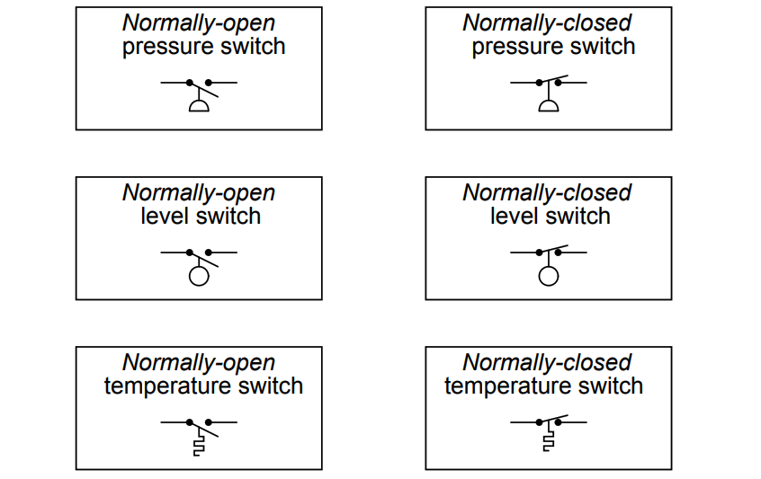
Things get more confusing, though, when we examine process switches, such as pressure switches, level switches, temperature switches, and flow switches:

Instrument Switch Status

Flow Switch Status

Define “normal” for each of these process switches. In other words, explain what condition(s) each process switch must be in to ensure it is in the “normal” state; and conversely, what condition(s) need to be applied to each switch to force it into its other state.

Answer :

The “normal” condition for a process switch is the condition of least stimulus.

For example:

  • A pressure switch will be in its “normal” state when there is minimum pressure applied
  • A level switch will be in its “normal” state when there is no level detected by the switch
  • A temperature switch will be in its “normal” state when it is cold
  • A flow switch will be in its “normal” state when there is no flow detected by the switch

Share Your Answers / comments.

Credits : by Tony R. Kuphaldt – under CC BY 1.0

Don't Miss Our Updates
Be the first to get exclusive content straight to your email.
We promise not to spam you. You can unsubscribe at any time.
Invalid email address
You've successfully subscribed !
Re-calibrate the Foxboro DP Pneumatic Transmitter
Questions on Resistive Tape Level Sensor
Programmable Logic Controller (PLC) Questions and Answers – 1
Draw the Symbols for Liquid Level Measuring Instruments
Analytical Process Control Question
Share This Article
Facebook Whatsapp Whatsapp LinkedIn Copy Link
Share
Leave a Comment

Leave a Reply Cancel reply

Your email address will not be published. Required fields are marked *

Stay Connected

128.3kFollowersLike
69.1kFollowersFollow
208kSubscribersSubscribe
38kFollowersFollow

Categories

Recent Comments

  • Guifty Shimica on Top Non-PLC Certification Courses for Automation Professionals
  • Guifty Shimica on Top Non-PLC Certification Courses for Automation Professionals
  • MIHARITSOA Aina Sitraka on Top Non-PLC Certification Courses for Automation Professionals
  • Vaishnavi on Free Instrumentation Course for Trainee Engineers

Related Articles

reactor vessel

Practical Process Control System Questions & Answers – 5

Vehicle Electrical Batteries upgrade

Upgrading the Electrical System in an Automobile

liquid flow control loop

Liquid Flow Control Loop Controller Action

Drum Level differential pressure transmitter

Calculate Differential Pressure Sensed by Level Transmitter

DP transmitter Errors

DP Transmitter Calibration Errors

Air Pressure Regulator cut-away diagram

Air Pressure Regulator Questions

PSV lift pressure

Calculate PSV Lift Pressure

burner management system P&ID

Solenoid Valves Questions & Answers – 1

More Articles

Electrical Machines Questions and Answers

Non-Salient Pole Machines Quiz

Self-actuated Temperature Regulator

Self-actuated Temperature Regulator – Principle, Types, Advantages

calibrating-and-testing-rtd-sensors

RTD Calibration Procedure

Compressor IP Case Discharge Temperature Gradually Increases

Compressor Anti-Surge Control near-miss incident

Difference between RTJ and T&G Flanges

Difference between RTJ and T&G Flange Facings

DO Analyzer Working Principle

Dissolved Oxygen Analyzer Working Principle

diode-basic-structure-symbol

Forward Bias & Reverse Bias of a Diode

Turbidity Sensor Calibration Procedure

Turbidity Sensor Calibration Procedure

Follow US
All rights reserved. Reproduction in whole or in part without written permission is prohibited.
Welcome Back!

Sign in to your account

Username or Email Address
Password

Lost your password?