Inst ToolsInst ToolsInst Tools
  • Courses
  • Automation
    • PLC
    • Control System
    • Safety System
    • Communication
    • Fire & Gas System
  • Instrumentation
    • Design
    • Pressure
    • Temperature
    • Flow
    • Level
    • Vibration
    • Analyzer
    • Control Valve
    • Switch
    • Calibration
    • Erection & Commissioning
  • Interview
    • Instrumentation
    • Electrical
    • Electronics
    • Practical
  • Q&A
    • Instrumentation
    • Control System
    • Electrical
    • Electronics
    • Analog Electronics
    • Digital Electronics
    • Power Electronics
    • Microprocessor
  • Request
Search
  • Books
  • Software
  • Projects
  • Process
  • Tools
  • Basics
  • Formula
  • Power Plant
  • Root Cause Analysis
  • Electrical Basics
  • Animation
  • Standards
  • 4-20 mA Course
  • Siemens PLC Course
Reading: DC Machines Terminology
Share
Font ResizerAa
Inst ToolsInst Tools
Font ResizerAa
  • Courses
  • Design
  • PLC
  • Interview
  • Control System
Search
  • Courses
  • Automation
    • PLC
    • Control System
    • Safety System
    • Communication
    • Fire & Gas System
  • Instrumentation
    • Design
    • Pressure
    • Temperature
    • Flow
    • Level
    • Vibration
    • Analyzer
    • Control Valve
    • Switch
    • Calibration
    • Erection & Commissioning
  • Interview
    • Instrumentation
    • Electrical
    • Electronics
    • Practical
  • Q&A
    • Instrumentation
    • Control System
    • Electrical
    • Electronics
    • Analog Electronics
    • Digital Electronics
    • Power Electronics
    • Microprocessor
  • Request
Follow US
All rights reserved. Reproduction in whole or in part without written permission is prohibited.
Inst Tools > Blog > Electrical Theory > DC Machines Terminology

DC Machines Terminology

Last updated: July 27, 2018 9:23 pm
Editorial Staff
Electrical Theory
No Comments
Share
2 Min Read
SHARE

DC Machines Terminology

Terminal Voltage

Terminal voltage, as applied to DC generators, is defined as the voltage that can be measured at the output of the generator.

Counter-Electromotive Force (CEMF)

In a generator using a rotating armature, the conductors cut the magnetic lines of force in the magnetic field. Voltage is induced in the armature conductors.

This induced voltage opposes the applied voltage; it counteracts some of the applied voltage, which reduces the current flow through the armature. This induced voltage acts counter to applied voltage; therefore, it is called counter-electromotive force (CEMF).

Applied Voltage

Applied voltage is defined as the voltage that is delivered across the load. This voltage should be the same as terminal voltage; however, various circuit faults and losses may reduce the terminal voltage.

Commutation

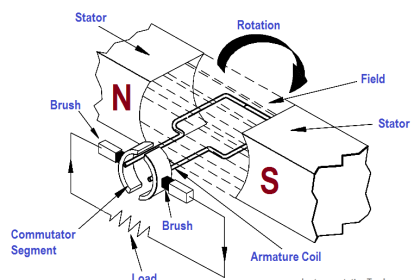
Commutation is the positioning of the DC generator brushes so that the commutator segments change brushes at the same time the armature current changes direction. More simply stated, commutation is the mechanical conversion from AC to DC at the brushes of a DC machine, as shown in Figure 1.

AC to DC Conversion with a Commutator

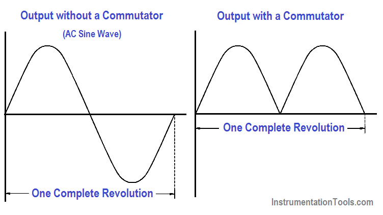
Figure 1 : AC to DC Conversion with a Commutator

In a DC generator, commutation provides for the conversion of AC to a DC output that is generated in the armature windings. Commutation will be discussed in greater detail in subsequent articles.

Don't Miss Our Updates
Be the first to get exclusive content straight to your email.
We promise not to spam you. You can unsubscribe at any time.
Invalid email address
You've successfully subscribed !

Continue Reading

Multimeter & Megger Principle
Power Factor
Battery Operation : Series and Parallel
Calculate Power in Series RC Circuit
Calculate Power in Parallel RCL Circuit
Unbalanced 3 Phase Loads
Share This Article
Facebook Whatsapp Whatsapp LinkedIn Copy Link
Share
Leave a Comment

Leave a Reply Cancel reply

Your email address will not be published. Required fields are marked *

Stay Connected

128.3kFollowersLike
69.1kFollowersFollow
210kSubscribersSubscribe
38kFollowersFollow

Categories

Explore More

Resonance, Resonant Frequency, Series and Parallel Resonance
Parallel Open Circuit Faults
Moving Iron Vane Meter Movement
AC Generator Nameplate Ratings
Half-Wave Rectifier Circuit
Induction Motor Torque Versus Slip
AC Induction Motor Slip
Power Factor Meter Principle

Keep Learning

Voltage and Current Phase Relationships in an Inductive Circuit

Voltage and Current Phase Relationships in an Inductive Circuit

Transformer Efficiency

Transformer Efficiency

3φ AC Power Connections

Three Phase Systems

Left-Hand Rule for Generators

DC Generator Theory

Wiring Diagram

Wiring Diagram

DC Machine

DC Machines Construction

Parallel Circuit Parallel Current Calculations

Parallel Circuit Current Calculations

Inductive Time Constant

Inductive Time Constant

Learn More

Delta WPL Soft Counter

Delta PLC Counter with Comparison

Function Module in Siemens PLC

What is Function Module in Siemens PLC?

How to Calibrate Load Cells

How to Calibrate Load Cells in Weighing Applications?

Chromatography Questions & Answers

High Pressure Liquid Chromatography Questions & Answers

Water Treatment Plant

Water Treatment Plant

Microwave Barrier Level Switch Working Principle

Centrifugal Compressor outage reduced

Centrifugal Compressor Outage Reduced – Root Cause Analysis

Electrical Machines Questions and Answers

Synchronous Machines Efficiency Questions

Menu

  • About
  • Privacy Policy
  • Copyright

Quick Links

  • Learn PLC
  • Helping Hand
  • Part Time Job

YouTube Subscribe

Follow US
All rights reserved. Reproduction in whole or in part without written permission is prohibited.
Welcome Back!

Sign in to your account

Username or Email Address
Password

Lost your password?