Inst ToolsInst ToolsInst Tools
  • Ask
  • Courses
  • Videos
  • Q & A
    • Interview
      • Instrumentation
      • Electronics
      • Electrical
      • Practical Questions
    • MCQ
      • Instrumentation MCQ
      • Electrical MCQ
      • Electronics MCQ
      • Control Systems MCQ
      • Analog Electronics MCQ
      • Digital Electronics MCQ
      • Power Electronics MCQ
      • Microprocessor MCQ
      • Multiple Choice Questions
  • EE
    • Electronics
      • Electronics Q & A
      • Electronic Basics
      • Electronic Devices & Circuits
      • Electronics Animation
      • Digital Electronics
    • Electrical
      • Electrical Basics
      • Electrical Q & A
      • Power Electronics
      • Electrical Machines
      • Electrical Animation
      • Power Systems
      • Switchgear & Protection
      • Transmission & Distribution
  • Measure
    • Control Valves
    • Calibration
    • Temperature
    • Pressure
    • Flow
    • Level
    • Analyzers
    • Switches
    • Vibration
    • Solenoid Valve
  • Control
    • PLC Tutorials
    • Control Systems
    • Safety Instrumented System (SIS)
    • Communication
    • Fire & Gas System
  • More
    • Design
    • Tools
    • Animation
    • Basics
    • Formulas
    • Standards
    • TextBooks
    • Common
    • Software
    • Excel Tools
    • Erection & Commissioning
    • Process Fundamentals
    • Videos
    • Books
Search
All rights reserved. Reproduction in whole or in part without written permission is prohibited.
Reading: Data Handling Instructions in PLC Programming
Share
Notification Show More
Font ResizerAa
Inst ToolsInst Tools
Font ResizerAa
  • Courses
  • PLC Tutorials
  • Control Systems
Search
  • Ask
  • Courses
  • Videos
  • Q & A
    • Interview
    • MCQ
  • EE
    • Electronics
    • Electrical
  • Measure
    • Control Valves
    • Calibration
    • Temperature
    • Pressure
    • Flow
    • Level
    • Analyzers
    • Switches
    • Vibration
    • Solenoid Valve
  • Control
    • PLC Tutorials
    • Control Systems
    • Safety Instrumented System (SIS)
    • Communication
    • Fire & Gas System
  • More
    • Design
    • Tools
    • Animation
    • Basics
    • Formulas
    • Standards
    • TextBooks
    • Common
    • Software
    • Excel Tools
    • Erection & Commissioning
    • Process Fundamentals
    • Videos
    • Books
Follow US
All rights reserved. Reproduction in whole or in part without written permission is prohibited.
Inst Tools > Blog > PLC Tutorials > Data Handling Instructions in PLC Programming

Data Handling Instructions in PLC Programming

Last updated: March 4, 2021 3:14 pm
Editorial Staff
PLC Tutorials
1 Comment
Share
4 Min Read
SHARE

We already discussed Timers, counters and other instructions used in PLC programming. Sometimes we may need some operations in the PLC programs which involve blocks of data operations. The instructions like timers and counters handle single bit of data, either 1 or 0.

Contents
Using MOV for Variable InitializationMasked Move (MVM) InstructionBitwise And (AND) InstructionClear (CLR) Instruction

The data handling instructions deals with more than a bit, like moving or transferring numbers from one memory location to another, comparing data values or performs simple arithmetic operations.

Move (MOV) Instructions

This output instruction moves the source value to the destination location. As long as the rung remains true, the instruction moves the data on each scan.
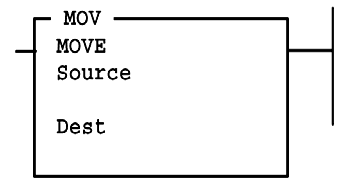
Move (MOV) Instruction in PLC

Entering Parameters

Source is the address or constant of the data you want to move.

Destination is the address where the instruction moves the data.

Application Note: If you wish to move one word of data without affecting the math flags, use a copy (COP) instruction with a length of 1 word instead of the MOV instruction.

Using MOV for Variable Initialization
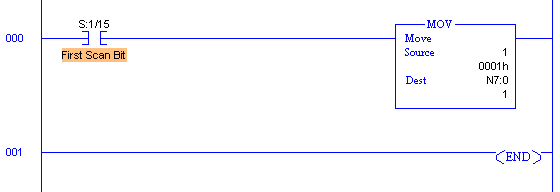
MOV Logic Example in PLC

S:1/15 is a bit in the status date file that is energized for exactly one PLC scan when the PLC is placed in run mode.

It Can be used to condition the initialization of variables used elsewhere in the ladder logic.

Masked Move (MVM) Instruction

The MVM instruction is a word instruction that moves data from a source location to a destination and allows portions of the destination data to be masked by a separate word.
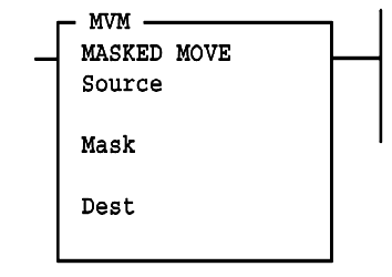
Masked Move (MVM)

As long as the rung remains true, the instruction moves the data on each scan.

Entering Parameters

Source is the address of the data you want to move.

Mask is the address of the mask through which the instruction moves data; the mask can be a hexadecimal value (constant).

Destination is the address where the instruction moves the data.

Read Also: PLC Example with MVM Instructions

Bitwise And (AND) Instruction

This instruction performs a bit-by-bit logical AND. The operation is performed using the value at source A and the value at source B. The result is stored in the destination.
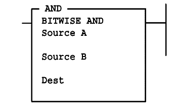
Bitwise AND

Source A and B can either be a word address or a constant; however, both sources cannot be a constant. The destination must be a word address.

Application Note: When entering constants, you can use the ampersand (&) operator to change the radix of your entry.

Instead of entering –1 as a constant, you could enter &B1111111111111111 or &HFFFF (Actual PLC only).

Nore – Use 1111111111111111B or FFFFH for the simulator purpose.

Read Also: Bitwise Logical Operations

Clear (CLR) Instruction

The CLR instruction is used to set the destination value of a word to zero.
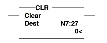
Clear (CLR) Instruction in PLC

This instruction always sets the Zero (Z) flag (S:0/2). Other arithmetic status bits are always cleared (reset)

  • S:0/0, carry (C)
  • S:0/1, overflow (V)
  • S:0/3, sign (S)

If you liked this article, then please subscribe to our YouTube Channel for PLC and SCADA video tutorials.

You can also follow us on Facebook and Twitter to receive daily updates.

Read Next:
Math Functions in PLC

Ladder Logic using Switches

Types of Instructions in PLC

VFD Control using PLC program

PLC Car Washing Control Logic

Don't Miss Our Updates
Be the first to get exclusive content straight to your email.
We promise not to spam you. You can unsubscribe at any time.
Invalid email address
You've successfully subscribed !
How to Read an Electrical Wiring Diagram?
Scheduled Daily Plant Watering PLC Program
Program Flow Control Instructions in PLC Programming
1 to 8 Demultiplexer PLC ladder diagram
PLC Ladder Logic for Sensor Scaling with Offset
Share This Article
Facebook Whatsapp Whatsapp LinkedIn Copy Link
Share
1 Comment
  • Rayfer says:
    September 6, 2019 at 6:27 pm

    very useful, thanks

    Reply

Leave a Reply Cancel reply

Your email address will not be published. Required fields are marked *

Stay Connected

128.3kFollowersLike
69.1kFollowersFollow
208kSubscribersSubscribe
38kFollowersFollow

Categories

Recent Comments

  • Guifty Shimica on Top Non-PLC Certification Courses for Automation Professionals
  • Guifty Shimica on Top Non-PLC Certification Courses for Automation Professionals
  • MIHARITSOA Aina Sitraka on Top Non-PLC Certification Courses for Automation Professionals
  • Vaishnavi on Free Instrumentation Course for Trainee Engineers

Related Articles

Create an Application in HMI using Tia Portal

Create an Application in HMI using Tia Portal

Leave Operational Logic in the PLC

#3 PLC Best Practices – Leave Operational Logic in the PLC wherever feasible

PLC Ladder Logic Chemical Mixing Process

Chemical Mixing Process using PLC

Case Statement in SCL Language

Case Statement in SCL Language

PLC Question Bank

PLC Question Bank

Communicate between the PLC program and HMI program

Design a Program Using Studio 5000 and FactoryTalk View Studio

Read Temperature in PLC

PLC Program to Read Temperature in PLC

Add an alarm display to the graphics.

How to Configure an Alarm in InTouch SCADA?

More Articles

Radiation Exposure Converter

Free Online Radiation Exposure Calculating Platform

Digital Electronics Multiple Choice Questions

Programmable Read Only Memory Objective Questions – Part 1

Tanks Draining Control in PLC using Functional Block Diagram

Tanks Draining Control in PLC using Functional Block Diagram

Steam Generator Parts

Parts and functions of Steam Turbine

Differential Pressure Sensor for Filtration Monitoring

Differential Pressure Sensor for Filtration Monitoring

Gang Switch Principle

Reading Electrical Schematics

Mechanical Torsion Meter Principle

Mechanical Torsion Meter Principle

Arc Fault Breaker (AFB) Electrical Problem Solved

Arc Fault Breaker (AFB) Electrical Problem Solved

Follow US
All rights reserved. Reproduction in whole or in part without written permission is prohibited.
Welcome Back!

Sign in to your account

Username or Email Address
Password

Lost your password?