Practical exercises with video solutions based on the conveyor and puncher PLC program using toggle switch and sensor.
Note: These PLC example logics are focused on students and fresh engineering graduates to learn the concepts.
Conveyor and Puncher PLC Program
Problem Statement:
Design a PLC ladder logic for the following application.
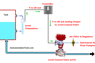
We are using one toggle switch and Sensor to control Conveyor and Puncher.
The Conveyor Should stop for 10 seconds and a Puncher will be ON for 2 seconds when a defect is detected.
Industrial Training Videos
The industrial training videos are useful for beginners to learn the programmable logic controllers.
Inputs and Outputs
Digital Inputs
Start Button: I0.0
Sensor: I0.1
Digital Outputs
Conveyor: Q0.0
Puncher: Q0.1
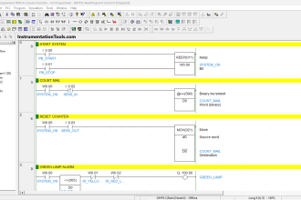
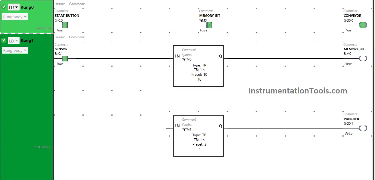
Ladder Diagram
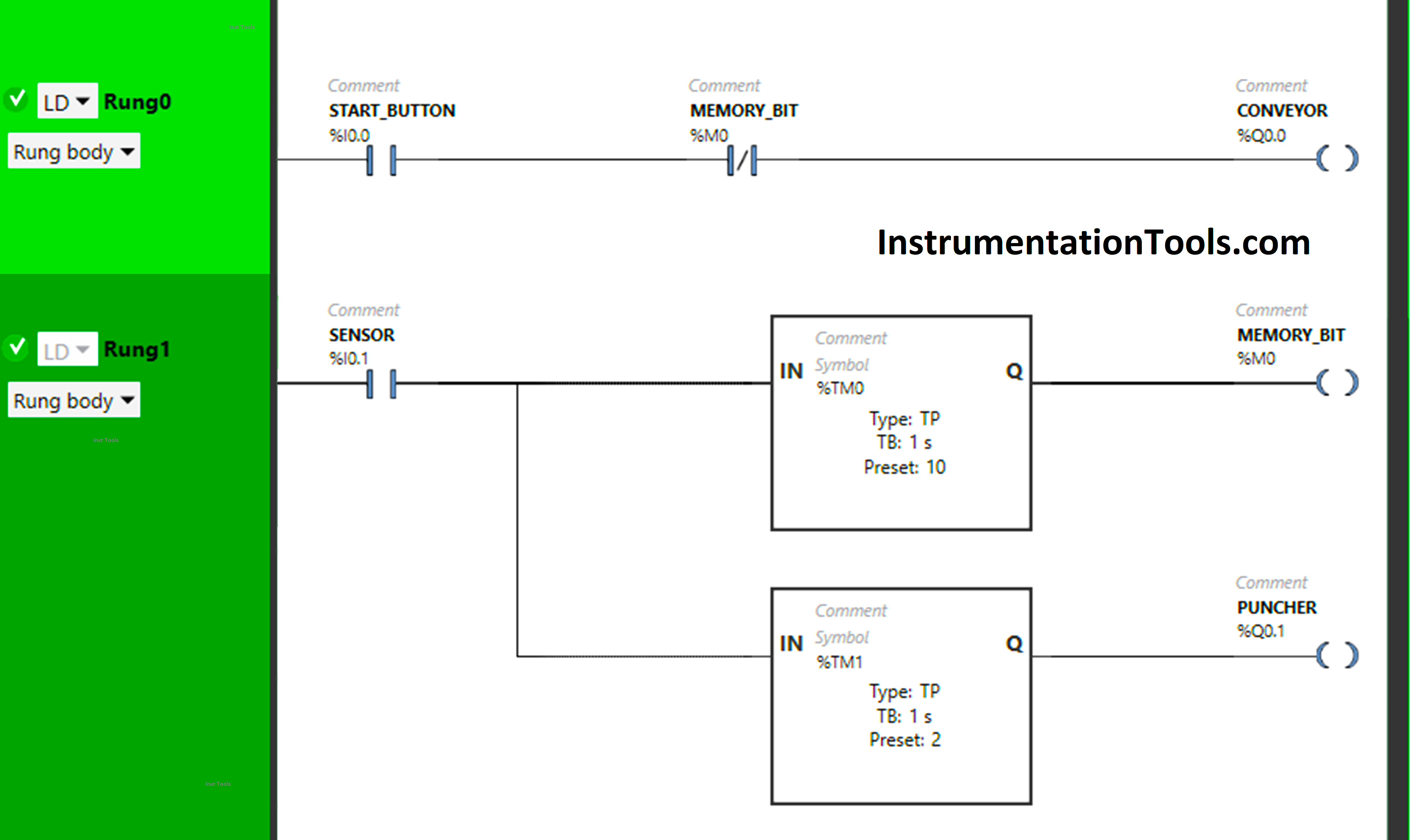
Program Description
We have used Normally Open Contacts for Start Button(I0.0) and Sensor (I0.1)
We have used Normally Closed Contact is used for Memory Bit (M0).
In Rung 0:
- Normally Open Contact is used for the Start Button (I0.0) to Turn ON the output Conveyor (Q0.0).
- Normally Closed Contact is used for Memory Bit (M0) to Turn OFF the output Conveyor (Q0.0).
In Rung 1:
- Normally Open Contact is used for Sensor (I0.1) to Turn ON Memory Bit (M0) and the output Puncher (Q0.1).
- TP timer is used to Turn ON the Memory Bit (M0) for a limited time.
- TP timer is used to Turn ON the output Puncher (Q0.1) for a limited time.
Simulation Results
Rung 0:
When the Start Button (I0.0) is turned ON, the output Conveyor (Q0.0) will turn ON as Normally Open Contact used for the Start Button (I0.0) passes the signal to turn ON the output Conveyor (Q0.0).
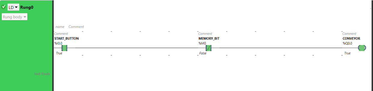
In a false state, Normally Closed Contact used for Memory Bit (M0) will also pass the signal to turn ON the output Conveyor (Q0.0).
Rung 1:
When Sensor (I0.1) gets activated, Memory Bit (M0) will turn ON for 10 seconds as Timer Function Block type TP is used to turn ON Memory Bit (M0) for a limited time. The time is set to 10 seconds. After 10 seconds, Memory Bit (M0) will turn OFF.
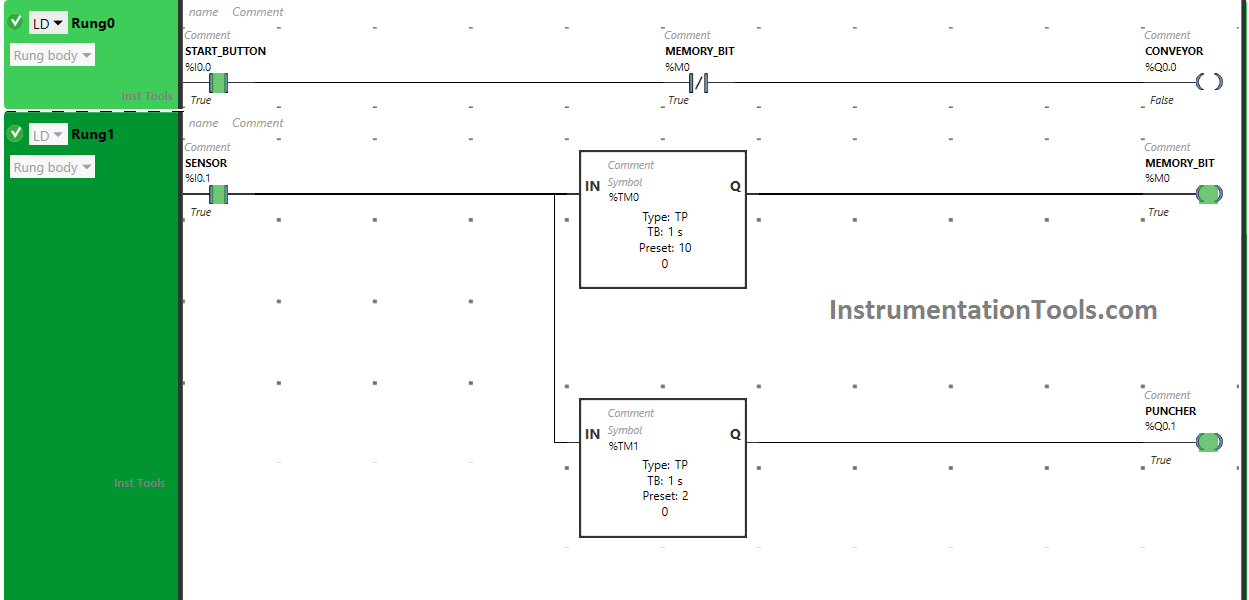
When Memory Bit (M0) turns ON in Rung1, Normally Closed Contact used for Memory Bit (M0) in Rung0 will be in a True state and does not allow the signal to flow, and the output Conveyor (Q0.0) will turn OFF.
Also, when Sensor (I0.1) gets activated, the output Puncher (Q0.1) will turn ON for 2 seconds as Timer Function Block type TP is used to turn ON the output Puncher (Q0.2) for a limited time. The time is set to 2 seconds. After 2 seconds, the output Puncher (Q0.1) will turn OFF.
When the first Timer Function Block type TP connected with Memory Bit (M0) reaches its set time i.e. 10 seconds, Memory Bit (M0) will turn OFF.
When Memory Bit (M0) turns OFF in Rung1, Normally Closed Contact used for Memory Bit (M0) in Rung0 will be in a false state and will pass the signal to turn ON the output Conveyor (Q0.0) again.
If you liked this article, please subscribe to our YouTube Channel for PLC and SCADA video tutorials.
You can also follow us on Facebook and Twitter to receive daily updates.
Read Next:
- Coffee Machine PLC Programming
- How to Blink Lights in Ladder Logic?
- PLC Example on Bottle Line Control
- Cooking Logic for Kitchen Automation
- PLC Ladder Logic Classroom Bell System