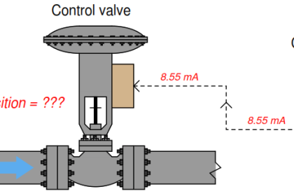
A Control Valve Positioner is a device used to increase or decrease the air load pressure driving the actuator until the valve’s stem reaches a “POSITION” balanced to the output SIGNAL from the process variable instrument controller.
Valve positioners are used on controlling valves where accurate and rapid control is required without error or hysterises.
Positioners are generally mounted on the side-yoke or top casing of the pneumatic actuator for linear sliding stem control valves, and at/near the end-of-shaft for rotary control vales.
For either basic design type, “mechanical feedback linkage” connected directly to the valve’s stem provides feedback to controller.
The process controller tells the positioner to “change” position; the feedback linkage reports back to the positioner confirming that a change has occurred and gives a “sense” of the magnitude of the change in position.
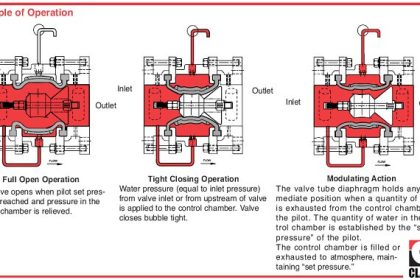
Principle of Operation
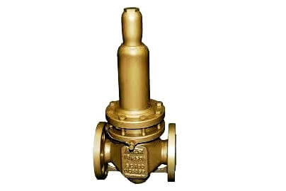
The Figure shows a valve positioner . The valve positioner is a force-balanced instrument, with pneumatic module installed on a double-acting actuator for air to open action. Positioning is based on a balance of two forces; one proportional to the instrument signal and the other proportional to the stem position.
A downward force is activated as the signal pressure acts upon the diaphragms in the instrument signal capsule, through the follower arm and cam, the motion of the actuator stem is transmitted to the top end of the feedback spring resulting in the varying of tension in feedback spring as stem position changes.
The system will be in equilibrium and stem will be in the position called for by the instrument signal when these opposing forces balance exactly. The balance will move up or down and by means of the spool valve, will change the output pressures and flow rate if these opposing forces are not in balance.
This will lead to the piston to moving until the tension on the feedback spring opposes exactly the instrument signal pressure.
Control Valve Positioner Working Principle

The detailed sequence of positioner operations are as follows :
- An increase in the instrument signal forces the instrument signal capsule and balance beam downward.
- This motion of the balance beam also pulls the pilot valve spool downward from its equilibrium position.
- This opens the pilot valve ports, supplying air to port 1 and exhausting air from port 2.
- This causes the actuator piston upward. Proportionally to the valve position, to counter the force generated by the instrument signal capsule, the piston continues to stroke upwards until force in the feedback spring increases sufficiently.
- At this point the balance beam and spool begin to return to equilibrium position.
- As the valve spool ports start to close, the air flow rate to the actuator is decreased.
- The feedback spring tension force will equal the force generated in the instrument signal capsule after the piston has reached the required position.
- The balance beam and instrument signal capsule will remain in their equilibrium positions with no air flowing to the actuator until a change in the instrument signal is made.
- A proportional downward movement of the actuator piston and stem is affected by a decrease in the instrument signal which reverses the described actions.
Control Valve Positioner Assembly
A valve positioner consists of a very high gain amplifier- this may be pneumatic, electro-pneumatic etc, and a feed back link which detects the actual position of the valve.

The required movement is for the valve to close. The input pressure from the controller to the bellows falls. The flapper moves away from the nozzle and the pressure after the orifice falls.
The pressure to the diaphragm falls and the valve begins to close. The feed back arm moves up rotating the cam clockwise. This raises the beam increasing back pressure in the nozzle until equilibrium is again achieved.
The change over cock allows the signal from the controller to be placed directly on the diaphragm
Valve Positioner Advantages
- Precise positioning
- can cope with large variations in forces acting on plug
- Rapid positioning
- Removes stiction and friction effects of gland
- Removes effects of large distances between valve and positioner
- Eliminates hysterises
When should a positioner be fitted
A positioner should be considered in the following circumstances:
- When accurate valve positioning is required;
- To speed up the valve response. The positioner uses higher pressure and greater air flow to adjust the valve position;
- To increase the pressure that a particular actuator and valve can close against. (To act as an amplifier);
- When the valve pressure drop at the maximum operating flowrate, exceeds 5 bar for single seated valves or 10 bar for double seated valves;
- To linearize a non-linear actuator;
- Where varying differential pressures within the fluid would cause the plug position to vary;
- When controlling with wide throttling range; and
- When valves are handling sludge or solids in suspension.
Also Read: Control Valve Working Animation


![Multi-Tank Liquid Level Control System with Fill Priority [PLC]](https://instrumentationtools.com/wp-content/uploads/2025/07/Multi-Tank-Liquid-Level-Control-System-with-Fill-Priority-PLC-330x220.jpg)


Again, a very good presentation of control valve positioner function. I would, however note that most Flapper/nozzle positioner types are two stage, where as the spool valve types are single stage. This is important because two stage incorporate a volume booster relay component that significantly increases gain. In the spool valve assemblies, the volume can only be increased by changing the size of the spool, therefore they are considered singe stage.
Nice presentation
Thanks for the share… A properly tuned positioner makes for tightly controlled loops, however an incorrectly mechanically positioned feedback arm will prevent stable control. Most important to make sure the arm is exactly horizontal at 50% position.
A “Positioner” is a Position Controller. Irrespective of what it’s actually driving, it is a Position Controller. It accepts a signal or Control Setpoint from AN Other Controller, hence it is a Cascade Function or Slave Controller. Position Feedback is available, irrespective of the the Positioner being an old Pneumatic Type or a New Electronic Smart Positioner.
@Tim Pegler, quite right re the Positioner Set-up, however is irrelevant if the function being driven is not correctly set-up, a Control Valve Motor and Valve Body must be correctly bench-set if it’s going to work at all
Sir, I am working as Inst.supervisor in kuwait KNPC under Kharafi national company. You are explaining very briefly and easy to understand. Thank you Sir
Thanks
Why positioner showing 9 VDC on multi meter display.
Must be Reply
Hi, Its due to voltage drop. check your branch cable and main cable resistance. You can ignore this voltage drop if your device working fine.
It Is So Important Pls Sent More About Instrumentetion And Control System
Thanks In Advance
am having 11 volts on my multimeter but the signal is not getting signal to open the valve
Hello Kodjo,
If your positioner is 24 volts then there is a lot of voltage drop.
Test your valve operation by using a external DC source using a source meter.
If control valves works without any issue then check the DCS or PLC cables / dropping voltage.
If you have any other control valves connected to the same junction box, then check the valve voltage for reference and compare, then proceed your troubleshooting accordingly.
How to calibrate and stroke Fisher positioner model 6200? Thank
m.azerbaijan20@gmail.com