Inst ToolsInst ToolsInst Tools
  • Courses
  • Automation
    • PLC
    • Control System
    • Safety System
    • Communication
    • Fire & Gas System
  • Instrumentation
    • Design
    • Pressure
    • Temperature
    • Flow
    • Level
    • Vibration
    • Analyzer
    • Control Valve
    • Switch
    • Calibration
    • Erection & Commissioning
  • Interview
    • Instrumentation
    • Electrical
    • Electronics
    • Practical
  • Q&A
    • Instrumentation
    • Control System
    • Electrical
    • Electronics
    • Analog Electronics
    • Digital Electronics
    • Power Electronics
    • Microprocessor
  • Request
Search
  • Books
  • Software
  • Projects
  • Process
  • Tools
  • Basics
  • Formula
  • Power Plant
  • Root Cause Analysis
  • Electrical Basics
  • Animation
  • Standards
  • 4-20 mA Course
  • Siemens PLC Course
Reading: Continuous Flow Measurement
Share
Font ResizerAa
Inst ToolsInst Tools
Font ResizerAa
  • Courses
  • Design
  • PLC
  • Interview
  • Control System
Search
  • Courses
  • Automation
    • PLC
    • Control System
    • Safety System
    • Communication
    • Fire & Gas System
  • Instrumentation
    • Design
    • Pressure
    • Temperature
    • Flow
    • Level
    • Vibration
    • Analyzer
    • Control Valve
    • Switch
    • Calibration
    • Erection & Commissioning
  • Interview
    • Instrumentation
    • Electrical
    • Electronics
    • Practical
  • Q&A
    • Instrumentation
    • Control System
    • Electrical
    • Electronics
    • Analog Electronics
    • Digital Electronics
    • Power Electronics
    • Microprocessor
  • Request
Follow US
All rights reserved. Reproduction in whole or in part without written permission is prohibited.
Inst Tools > Blog > Flow Measurement > Continuous Flow Measurement

Continuous Flow Measurement

The Continuous measurement of fluid flow is arguably the single most complex type of process variable measurement in all of industrial instrumentation.

Last updated: November 1, 2023 2:01 pm
Editorial Staff
Flow Measurement
No Comments
Share
4 Min Read
SHARE

The measurement of fluid flow is arguably the single most complex type of process variable measurement in all industrial instrumentation.

Not only is there a bewildering array of technologies one might use to measure fluid flow – each one with its own limitations and idiosyncrasies – but the very nature of the variable itself lacks a singular definition.

Flow Measurement

Flow Measurement

“Flow” may refer to volumetric flow (the number of fluid volumes passing by per unit time), mass flow (the number of fluid mass units passing by per unit time), or even standardized volumetric flow (the number of gas volumes flowing, supposing different pressure and temperature values than what the actual process line operates at).

Flow meters configured to work with gas or vapor flows often are unusable on liquid flows. The dynamic properties of the fluids themselves change with flow rates.

Most flow measurement technologies cannot achieve respectable measurement linearity from the maximum rated flow all the way to zero flow, no matter how well-matched they might be to the process application.

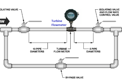
Furthermore, the performance of most flow meter technologies critically depends on proper installation.

One cannot simply hang a flow meter at any location in a piping system and expect it to function as designed. This is a constant source of friction between piping (mechanical) engineers and instrumentation (controls) engineers on large industrial projects.

What might be considered an excellent piping layout from the perspective of process equipment function and economy is often poor (at best) for good flow measurement, and vice-versa. In many cases, the flowmeter equipment gets installed improperly and the instrument technicians have to deal with the resulting measurement problems during process unit start-up.

Even after a flow meter has been properly selected for the process application and properly installed in the piping, problems may arise due to changes in process fluid properties (density, viscosity, conductivity), or the presence of impurities in the process fluid.

Flowmeters are also subject to far more “wear and tear” than most other primary sensing elements, given the fact that a flowmeter’s sensing element(s) must lie directly in the path of potentially abrasive fluid streams.

Given all these complications, it is imperative for instrumentation professionals to understand the complexities of flow measurement. What matters most is that you thoroughly understand the physical principles upon which each flowmeter depends. If the “first principles” of each technology are understood, the appropriate applications and potential problems become much easier to recognize.

If you liked this article, then please subscribe to our YouTube Channel for Instrumentation, Electrical, PLC, and SCADA video tutorials.

You can also follow us on Facebook and Twitter to receive daily updates.

Read Next:

  • Ultrasonic Doppler Flow Meter
  • What is Averaging Pitot Tube?
  • Industrial Instrumentation Quiz
  • Wedge Flow Meter Principle
  • Standardized Volumetric Flow
Don't Miss Our Updates
Be the first to get exclusive content straight to your email.
We promise not to spam you. You can unsubscribe at any time.
Invalid email address
You've successfully subscribed !

Continue Reading

Troubleshooting Magnetic Flow Meters Common Problems
Turbine Flow Meter – Principle, Advantages, Disadvantages
What Factors Affect the Stability of Flow Meter Readings?
Measure Flow rate using Level Sensors
Ultrasonic Doppler Flow Meter Advantages and Disadvantages
Types of Variable Area Flow Meters
Share This Article
Facebook Whatsapp Whatsapp LinkedIn Copy Link
Share
Leave a Comment

Leave a Reply Cancel reply

Your email address will not be published. Required fields are marked *

Stay Connected

128.3kFollowersLike
69.1kFollowersFollow
210kSubscribersSubscribe
38kFollowersFollow

Categories

Explore More

Importance of Magnetic Flow Meters Grounding
V Cone Flow Meter – Principle, Advantages, Disadvantages
What is a Turbine Flow Meter?
Orifice Plate Questions and Answers
Design Considerations of Orifice Plate
Facts About Orifice Flow Meters
Swirl Flow Meters Working Principle
What is the Purpose of Orifice Plate Drain Hole and Vent Hole?

Keep Learning

Orifice Beta

Why is Orifice Beta in between 0.3 to 0.7?

Linear to Square Root Extraction

ROTARY ABUTMENT FLOW METERS WORKING ANIMATION

Rotary Abutment Flow Meters Working Principle and Animation

Vortex Flow Meter Animation

Basic Working Principle of Vortex Flowmeter

Flow Switch Principle

In-Line Flow Switch Working Principle and Animation

Laminar Flow Meter Working Principle

Laminar Flow Meter Working Principle

Flowmeter Characteristics

Flow Meter Characteristics

Reciprocating Piston Meters

Overview of Positive Displacement Flow Meters

Learn More

Electronic Devices & Circuits Objective Questions

Electronic Devices & Circuits Quiz – Set 15

Field Instruments Selection Aid

Field Instruments Selection Aid

Digital Control Systems

Compensation Techniques : Control Systems

Impulse Line Purging and Close Coupling

Impulse Line Purging and Close Coupling of Instruments

Electrical Ladder Diagram Control using Timers Example

Electrical Ladder Diagram Control using Timers Example

Fence grounding specifications

All About Electric Fence Gates

Sources of Static Grounding and Methods to Control

Sources of Static Grounding and Methods to Control

What is Gas Chromatography

What is Gas Chromatography?

Menu

  • About
  • Privacy Policy
  • Copyright

Quick Links

  • Learn PLC
  • Helping Hand
  • Part Time Job

YouTube Subscribe

Follow US
All rights reserved. Reproduction in whole or in part without written permission is prohibited.
Welcome Back!

Sign in to your account

Username or Email Address
Password

Lost your password?