Inst ToolsInst ToolsInst Tools
  • Courses
  • Automation
    • PLC
    • Control System
    • Safety System
    • Communication
    • Fire & Gas System
  • Instrumentation
    • Design
    • Pressure
    • Temperature
    • Flow
    • Level
    • Vibration
    • Analyzer
    • Control Valve
    • Switch
    • Calibration
    • Erection & Commissioning
  • Interview
    • Instrumentation
    • Electrical
    • Electronics
    • Practical
  • Q&A
    • Instrumentation
    • Control System
    • Electrical
    • Electronics
    • Analog Electronics
    • Digital Electronics
    • Power Electronics
    • Microprocessor
  • Request
Search
  • Books
  • Software
  • Projects
  • Process
  • Tools
  • Basics
  • Formula
  • Power Plant
  • Root Cause Analysis
  • Electrical Basics
  • Animation
  • Standards
  • 4-20 mA Course
  • Siemens PLC Course
Reading: Conductivity Transmitter Calibration Procedure
Share
Font ResizerAa
Inst ToolsInst Tools
Font ResizerAa
  • Courses
  • Design
  • PLC
  • Interview
  • Control System
Search
  • Courses
  • Automation
    • PLC
    • Control System
    • Safety System
    • Communication
    • Fire & Gas System
  • Instrumentation
    • Design
    • Pressure
    • Temperature
    • Flow
    • Level
    • Vibration
    • Analyzer
    • Control Valve
    • Switch
    • Calibration
    • Erection & Commissioning
  • Interview
    • Instrumentation
    • Electrical
    • Electronics
    • Practical
  • Q&A
    • Instrumentation
    • Control System
    • Electrical
    • Electronics
    • Analog Electronics
    • Digital Electronics
    • Power Electronics
    • Microprocessor
  • Request
Follow US
All rights reserved. Reproduction in whole or in part without written permission is prohibited.
Inst Tools > Blog > Analyzers > Conductivity Transmitter Calibration Procedure

Conductivity Transmitter Calibration Procedure

Last updated: March 4, 2019 11:09 pm
Editorial Staff
Analyzers Calibration Guest Articles
4 Comments
Share
5 Min Read
SHARE

In this article, we discuss about How calibration is to be performed through decade resistance box for a conductivity transmitter.

conductivity transmitter

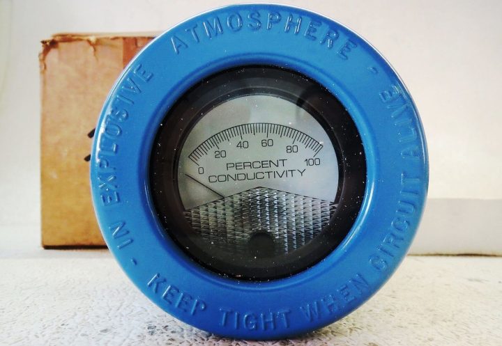
Image courtesy : Emerson analytical

Theory :

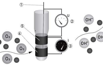
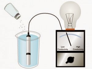
Conductivity is the ability of any solution to pass a electric current. In any liquid current is carried by cation and anions.

Conductivity of any solution is depending on following factors:

  1. Concentration
  2. Mobility of ions
  3. Valence of ions
  4. Temperature

The unit of conductivity is micro-Siemens per centimeter or µS/cm.

Need of conductivity measurement:

  1. To detect the leak in a process vessel: Water used for cooling in heat exchangers and surface condensers for temperature control. If any Leakage occurred in vessel tube which mix the cooling water into the process liquid and can result in potentially harmful contamination. Its can detect by conductivity measurement
  2. Conductivity is used to monitor the buildup of dissolved ionic solids in evaporative cooling water systems and in boilers.
  3. Water treatment facilities

Calibration of Conductivity Transmitter :

Calibration can be done by two methods.

  1. With standard sample
  2. With resistance decade box

Here we are discussing calibration with resistance decade box.

And consider Emerson make conductivity analyser or transmitter and model number is 1181T.

Formula to find out the resistance :

As we are discussing about calibration via a decade resistance box, we need to calculate the equivalent resistance which to be applied from a decade resistance box to the conductivity transmitter for the calibration purpose. As per our process temperature range, we have three different types of formulas for the resistance calculations.

The three formulas as per process temperature range are :

  1. If your sample temperature is in between 5 to 85 deg C

Resistance (conductivity) = Probe Constant X 1,000,000 / F.S. Conductivity

  1. If your sample temperature is in between 50 to 150 deg C

Resistance (conductivity) = 0.4 X Probe Constant X 1,000,000 / F.S. Conductivity

  1. If your sample temperature is in between 100 to 200 deg C

Resistance (conductivity) = 0.4 X Probe Constant X 1,000,000 / F.S. Conductivity

In our discussions, we considered sample temperature is in between 0 – 50 deg Celsius. so first formula is applied in our below example.

Calibration Example :

Suppose a conductivity transmitter calibration to be carried out which has range 0 – 100 µS/cm and cell constants 0.1

Solution:

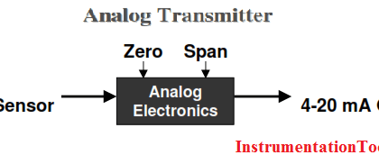
For any transmitter, there are two minimum calibration checks will be there.

They are

  1. Zero Calibration : For verifying the zero reading of the transmitter
  2. Span Calibration : For verifying the calibrated range of the transmitter

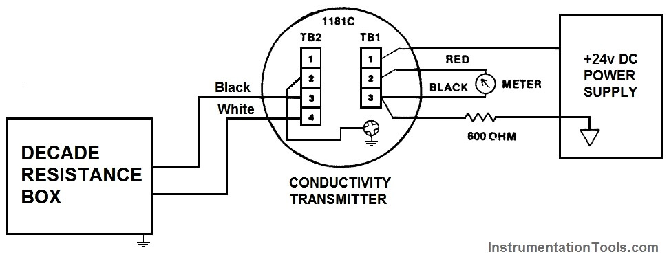
Connect the decade box and power supply as shown in below figure.

conductivity transmitter wiring

Zero calibration :

For Zero calibration : remove/disconnect the decade resistance box and adjust the transmitter to 4 ma for Zero reading.

Span calibration :

  • First calculate the required resistance for the span calibration.

Resistance (conductivity) = Probe Constant X 1,000,000 / F.S. Conductivity

= 0.1 X 1,000, 000 / 100 ohm = 1000 ohm = 1 kilo ohm

  • Connect Decade resistance box to the transmitter
  • Adjust the resistance to 1 kilo ohms (as calculated above).
  • Check the current output of transmitter & it has to show 20mA otherwise adjust.

Middle point calibration :

we can also do a intermediate calibration check of the 4-20mA transmitter range.

Here we considered 12mA for the calibration purpose.

So again calculate the resistance for the middle point calibration

Resistance = 2 X full scale resistance conductivity

= 2 X 1000 ohm = 2 kilo ohm

  • Connect Decade resistance box to the transmitter
  • Adjust the resistance to 2 kilo ohms (as calculated above).
  • Check the current output of transmitter & it has to show 12 ma ( ±0.16mA ) otherwise adjust.

Reference : Emerson analytical

Article by :
Ashish Agrawal
Don't Miss Our Updates
Be the first to get exclusive content straight to your email.
We promise not to spam you. You can unsubscribe at any time.
Invalid email address
You've successfully subscribed !

Continue Reading

How to Calibrate Temperature Switch? – Instrument Basics
Magnetostrictive Level Transmitter Calibration Procedure
Moisture Calculator
Control Valve Cavitation and Flashing
Online Gas Chromatograph Principle
Difference between Accuracy, Tolerance, Uncertainty, and Error
Share This Article
Facebook Whatsapp Whatsapp LinkedIn Copy Link
Share
4 Comments
  • Dirk Horst says:
    January 7, 2018 at 11:31 am

    This described method is not correct.
    First of all it is assumed that the sample (process) temperature dependency alva is linear in particular temperature ranges. This may be acceptable valid for most of the water applications but certainly not for many other processes !
    Then the cell constant K is also not explained how to choose the correct K value based on the measuring range of conductivity!
    A far better full explanation is given by Yogogawa, who took it from earlier Electrofact.
    Any comment, please contact me.

    Reply
    • Kuldeep says:
      January 7, 2018 at 3:15 pm

      Mostly we measure the conductivity of water which is used in heat exchanger and in this article describe how to calibrate so k value is already given with sensor and transmitter

      Reply
  • subham kalita says:
    June 1, 2018 at 12:07 pm

    Which formula to be used if sample temp is in between 50 to 80 degree celcius?

    Reply
  • chinmay says:
    August 9, 2023 at 8:05 am

    which method is used to calibrate the toroidal conductivity analyzer?
    Option A) with probe discounted ,connect decade resistance box across the input terminal , then dial a desire resistance.
    B) with probe disconnected loop a wire toroidal , attached decade resistance box, then in desire resistance

    Reply

Leave a Reply Cancel reply

Your email address will not be published. Required fields are marked *

Stay Connected

128.3kFollowersLike
69.1kFollowersFollow
210kSubscribersSubscribe
38kFollowersFollow

Categories

Explore More

DP Transmitter Dry Leg & Wet Leg Calculations
Compressor & Compressor Valves Maintenance
Displacer (buoyancy) Level Transmitter Principle, Limitations, Design, Installation & Calibration
Calibration Procedure of Weighing Balance and Common Mistakes
How are HART instruments Calibrated?
DeadWeight Tester Questions
Impulse Line Pressure Testing Procedure
Two Electrode Conductivity Probes Principle

Keep Learning

ORP-sensor-calibration

Oxidation-Reduction Potential (ORP) Sensor Calibration Procedure

Flow Meter Calibration Procedure

Flow Meter Calibration

Automatic Liquid Mixing Application

PLC Program for Automatic Liquid Mixing Application

PLC Program for Sequential Motor Control

PLC Program for Sequential Motor Control

PLC Program for Water filling and Discharging Process

PLC Program for Water filling and Discharging Process

pH Analyzer Do’s and Don’ts

pH Analyzer Do’s and Don’ts

Gas Detectors Calibration

Calibration of Gas Detectors

Conductivity Analyzer Principle

Conductivity Analyzers Interview Questions & Answers

Learn More

Analyzers Questions and Answers

Paramagnetic Oxygen Analyzers Questions & Answers

What is PLC Redundancy

What is PLC Redundancy?

Basics of Motion Controllers

Basics of Motion Controllers

Spectrometers Questions and Answers

Fluorescent Spectrometer Questions & Answers

PLC Subroutine

Allen Bradley PLC Subroutines

Rate of Rise Thermal Detectors Working Principle

Rate of Rise Thermal Detectors Working Principle

Siemens Industrial Laptop (Simatic Field PG)

Connect to the Siemens S7 PLC

Electrical Machines Questions and Answers

Commutator Action Quiz

Menu

  • About
  • Privacy Policy
  • Copyright

Quick Links

  • Learn PLC
  • Helping Hand
  • Part Time Job

YouTube Subscribe

Follow US
All rights reserved. Reproduction in whole or in part without written permission is prohibited.
Welcome Back!

Sign in to your account

Username or Email Address
Password

Lost your password?