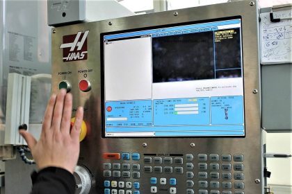
Computer Numerical Control (CNC) programming is a method used by manufacturers to create program instructions for computers to control a CNC machine.
This CNC programming is highly involved in the manufacturing process to improve automation and increase flexibility.
What are the types of codes available in CNC programming?
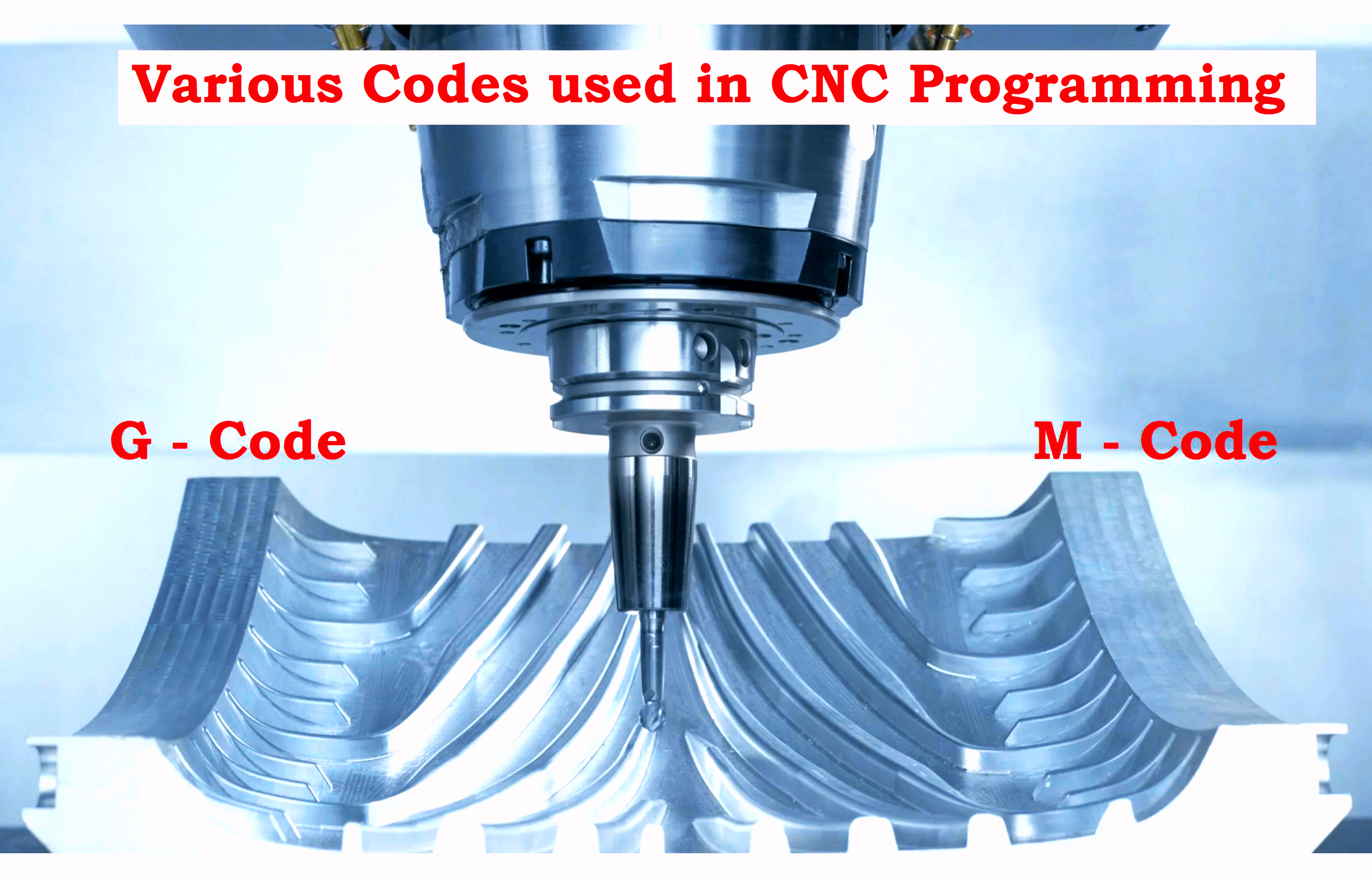
- A CNC program uses two types of codes G-code and M-code.
- G-code to run CNC mills, while
- M-codes are for routers.
- Both these types of codes are necessary for programming a CNC machine for various processes.
What is G Code?
A G code in CNC programming controls the machine movements to define how and where a machine should move to fabricate a part.
What is M Code?
An M code in CNC programming controls miscellaneous machine functions, including starting and stopping actions of the machine.
G-Codes and M-Codes used in CNC programming
Both these G-Codes and M-Codes work together to manufacture essential parts and components in the manufacturing and industrial sectors.
How to Read G Codes?
- G code file breaks lengthy complicated contents into Cartesian coordinates and markers.
- Each string of numbers has an order, and the G codes follow a careful structure to carry out their functions properly.
- Use a key to remind a forgotten code by looking at codes you are most familiar with.
How to Read M Codes?
- M (Miscellaneous) codes are supplemented by other category codes to activate the ideal setting of the CNC machine.
- This lines with M codes although they are structured in a specific order to keep processes running smoothly.
- An S code can set the spindle speed as it is moved with an M code,
- for example. M codes are often used with G codes to operate a machine effectively.
The most common G-codes and M-codes used for CNC programming are shown below.
Common G-Codes
G00 Rapid move G0 X# Y# Z# up to eight axes or G0 Z# X#
G01 Feed Rate move G1 X# Y# Z# up to eight axes or G1 Z# X#
G02 Clockwise Circular or Helical Interpolation Move
G03 Counter Clockwise Circular or Helical Interpolation Move
G04 Dwell time G04 L#
G07 Lathe Diameter Mode
G08 Spline Smoothing On
G09 Exact stops check, Spline Smoothing Off
G10 linear feed rate controlled to move with a decelerated stop
G11 Controlled Coordinate System Origin Setting (Decel stop)
G17 XY Plane Selection
G18 XZ Plane Selection
G19 YZ Plane Selection
G20 Inch System Selection
G21 Millimeter System Selection
G28 Return to Clearance Plane
G33 Threading (Lathe)
G33 and G33.1 will not work on some CNC mills or lathes due to no synchronization between the spindle and the axis.
G35 Bypass Error Checking On Next Line
G40 Cancel Cutter Diameter Compensation
G41 Start Cutter Tool Diameter Compensation to Left
G42 Start Cutter Tool Diameter Compensation to Right
G43 Tool Length Compensation – Negative Direction
G44 Tool Length Compensation – Positive Direction
G49 Tool Length Compensation Canceled
G53 Cancel Motion in Machine Work Coordinate System Offsets
G54 Use Preset Work Coordinate System 1
G55 Use Preset Work Coordinate System 2
G56 Use Preset Work Coordinate System 3
G57 Use Preset Work Coordinate System 4
G58 Use Preset Work Coordinate System 5
G59 Use Preset Work Coordinate System 6
G59.1 Use Preset Work Coordinate System 7
G59.2 Use Preset Work Coordinate System 8
G59.3 Use Preset Work Coordinate System 9
G61 Spline Contouring With Buffering Mode Off
G64 Spline Contouring With Buffering Mode On
G65 Mill out Rectangular Pocket
G66 Mill out Circular Pocket
G67 Fly cut
G68 Mill out rectangular pocket with radius corners
G70 Inch mode
G71 Millimeter mode
G74 Peck drilling (Lathe) G83 Z# X# R#
G80 Cancel Motion Mode
G81 Drill cycle G81 X# Y# Z# R#
G82 Dwell cycle G82 X# Y# Z# R#
G83 Chip Breaking Peck cycle G83 X# Y# Z# R#
G84 Right Hand Tapping cycle G84 X# Y# Z# R# C#
G85 Feed out Canned Boring cycle 1 G85 X# Y# Z# R#
G86 Boring Spindle Stop, Rapid out Cycle 2 G86 X# Y# Z# R#
G87 Back Boring Canned Cycle
G88 Boring Spindle Stop, Manual cycle 3 G88 X# Y# Z# R#
G89 Boring feed out canned cycle 4 G89 X# Y# Z# R#
G90 Absolute Distance Mode
G91 Incremental Distance Mode
G92 Home coordinate system reset G92 X# Y# Z#
G92.2 Cancel Offset Coordinate Systems
G93 Inverse Time Feed Mode
G94 Feed per Minute Mode IPM mode (Lathe) default
G95 IPR mode (Lathe)
G96 Constant Surface Feed On (Lathe)
G97 Constant Surface Feed off (Lathe)
G98 Initial Level Return in Canned Cycles
G99 “R” Level Return In Canned Cycles
Common M-Codes
For most CNC machines,
User-customizable M codes can be changed based on application and user definition
Some default M-codes used are
M00 Program Stop
M01 Program Optional Stop
M02 End the Program
M03 Spindle On Clockwise, Laser, Flame, Power ON
M04 Spindle On Counter Clockwise
M05 Spindle Stop, Laser, Flame, Power OFF
M06 Tool Change
M08 Coolant On
M09 Coolant Off
M10 Reserved for tool height offset
M13 Spindle On, Coolant On
M30 End the Program when macros are used
M91 Readout Display Incremental
M92 Readout Display Absolute
M97 Go to or jump to line number
M98 Jump to macro or subroutine
M99 Return from macro or subroutine
M100 Machine Zero Reset
M199 Mid-program start.
