Inst ToolsInst ToolsInst Tools
  • Courses
  • Automation
    • PLC
    • Control System
    • Safety System
    • Communication
    • Fire & Gas System
  • Instrumentation
    • Design
    • Pressure
    • Temperature
    • Flow
    • Level
    • Vibration
    • Analyzer
    • Control Valve
    • Switch
    • Calibration
    • Erection & Commissioning
  • Interview
    • Instrumentation
    • Electrical
    • Electronics
    • Practical
  • Q&A
    • Instrumentation
    • Control System
    • Electrical
    • Electronics
    • Analog Electronics
    • Digital Electronics
    • Power Electronics
    • Microprocessor
  • Request
Search
  • Books
  • Software
  • Projects
  • Process
  • Tools
  • Basics
  • Formula
  • Power Plant
  • Root Cause Analysis
  • Electrical Basics
  • Animation
  • Standards
  • 4-20 mA Course
  • Siemens PLC Course
Reading: Cathode Ray Tube Deflection System
Share
Font ResizerAa
Inst ToolsInst Tools
Font ResizerAa
  • Courses
  • Design
  • PLC
  • Interview
  • Control System
Search
  • Courses
  • Automation
    • PLC
    • Control System
    • Safety System
    • Communication
    • Fire & Gas System
  • Instrumentation
    • Design
    • Pressure
    • Temperature
    • Flow
    • Level
    • Vibration
    • Analyzer
    • Control Valve
    • Switch
    • Calibration
    • Erection & Commissioning
  • Interview
    • Instrumentation
    • Electrical
    • Electronics
    • Practical
  • Q&A
    • Instrumentation
    • Control System
    • Electrical
    • Electronics
    • Analog Electronics
    • Digital Electronics
    • Power Electronics
    • Microprocessor
  • Request
Follow US
All rights reserved. Reproduction in whole or in part without written permission is prohibited.
Inst Tools > Blog > Electronic Devices & Circuits > Cathode Ray Tube Deflection System

Cathode Ray Tube Deflection System

Last updated: April 1, 2018 8:32 am
Editorial Staff
Electronic Devices & Circuits
No Comments
Share
4 Min Read
SHARE

This Post Deflection system of CRT is a continuation of my previous post Electron Gun of CRT. This post completely covers the Deflection system of the CRT. When the electron beam is accelerated it passes through the deflection system, with which beam can be positioned anywhere on the screen.

The deflection system of the cathode-ray-tube consists of two pairs of parallel plates, referred to as the vertical and horizontal deflection plates. One of the plates in each set is connected to ground (0 V). to the other plate of each set, the external deflection voltage is applied through an internal adjustable gain amplifier stage. To apply the deflection voltage externally, an external terminal, called the y input or the x input, is available.

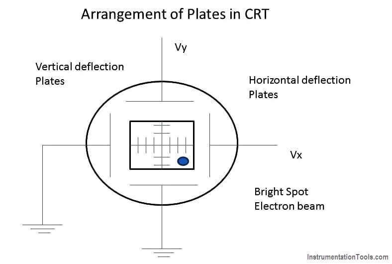
As shown in the image below, the electron beam passes through these plates. A positive voltage applied to the y input terminal (V y) causes the beam to deflect vertically upward due to the attraction forces, while a negative voltage applied to the y-input terminal will cause the electron beam to deflect vertically downward, due to the repulsion forces.

Similarly, a positive voltage applied to X-input terminal(V x) will cause the electron beam to deflect horizontally towards the right; while a negative voltage applied to the X-input terminal will cause the electron beam to deflect horizontally towards the left of the screen. The amount of vertical or horizontal deflection is directly proportional to the corresponding applied voltage.

When the voltages are applied simultaneously to vertical and horizontal deflecting plates, the electron beam is deflected due to the resultant of these two voltages.

The face of the screen can be considered as an X-Y plane. The (X,Y) position of the beam spot is thus directly influenced by the horizontal and the vertical voltages applied to the deflection plates Vx and Vy respectively.

The horizontal deflection (X) produced will be proportional to the horizontal deflecting voltage, Vx, applied to X-input.

X = KxVx

Where, Kx is constant of proportionality.

The deflection produced is usually measured in cm or as number of division , on the scale, in the horizontal direction.

Then Kx = x/Vx where Kx expressed as cm/volt or division/volt, is called horizontal sensitivity of the oscilloscope.

Similarly, the vertical deflection (y) produced will be proportional to the vertical deflecting voltage, Vy, applied to the y-input.
Y= KyVy

Ky=y/Vy and Ky, the vertical sensitivity, will be expressed as cm/volt, or division/volt.

The schematic arrangement of the vertical and the horizontal plates controlling the position of the spot on the screen is shown in the figure.

Cathode Ray Tube Deflection System

The values of vertical and horizontal sensitivities are selectable and adjustable through multi positional switches on the front panel that controls the gain of the corresponding internal amplifier stage. The bright spot of the electron beam can thus trace (or plot) the X-Y relationship between the two voltages, Vx and Vy.

Don't Miss Our Updates
Be the first to get exclusive content straight to your email.
We promise not to spam you. You can unsubscribe at any time.
Invalid email address
You've successfully subscribed !

Continue Reading

Seven Segment Display Working Principle
Tunnel Diode Working Principle
Full Wave Bridge Rectifier Peak Inverse Voltage
Energy Diagrams of PN Junction & Depletion Region
Transistor Collector Feedback Bias
Difference between Schottky Diode and PN junction Diode
Share This Article
Facebook Whatsapp Whatsapp LinkedIn Copy Link
Share
Leave a Comment

Leave a Reply Cancel reply

Your email address will not be published. Required fields are marked *

Stay Connected

128.3kFollowersLike
69.1kFollowersFollow
210kSubscribersSubscribe
38kFollowersFollow

Categories

Explore More

Basic DC Power Supply Circuit
Semiconductors Diodes Questions & Answers
JFET Working Animation
Comparison of Transistor Configurations
Series and Parallel Resistors
Half Wave Voltage Doubler using Diodes
Basics of Transistors
How to Test a Diode using Multimeter

Keep Learning

Transistor Load Line Analysis

Transistor Load Line Analysis

MOSFET VI Characteristics

Power MOSFET

Open Circuit without Freewheeling diode

Freewheeling Diode Working Principle

Short Circuit and Open Circuit

Short Circuit and Open Circuit

Fluorescent Screen of CRT

CRT Fluorescent Screen

Derivation-of-Ohms-Law

Basics of Ohm’s Law

Comparison of MOSFET and BJT

Comparison of MOSFET and BJT

phototransistor-circuit

Phototransistor Circuit Example

Learn More

Arc Fault Breaker (AFB) Electrical Problem Solved

Arc Fault Breaker (AFB) Electrical Problem Solved

Thermowell Immersion Length

Thermowell Insertion and Immersion Length

DP-Level-Transmitter-Open-tank-calibration

Open Tank DP Level Transmitter Calibration

Generator Action in a Motor

Generator Action in a Motor

DeadWeight Tester

DeadWeight Tester Questions

BALL CHECK VALVE THEORY

Types of Check Valves

Steam Generator Parts

Parts and functions of Steam Turbine

Synchronous Motor Principle

Synchronous Motors

Menu

  • About
  • Privacy Policy
  • Copyright

Quick Links

  • Learn PLC
  • Helping Hand
  • Part Time Job

YouTube Subscribe

Follow US
All rights reserved. Reproduction in whole or in part without written permission is prohibited.
Welcome Back!

Sign in to your account

Username or Email Address
Password

Lost your password?