Inst ToolsInst ToolsInst Tools
  • Courses
  • Automation
    • PLC
    • Control System
    • Safety System
    • Communication
    • Fire & Gas System
  • Instrumentation
    • Design
    • Pressure
    • Temperature
    • Flow
    • Level
    • Vibration
    • Analyzer
    • Control Valve
    • Switch
    • Calibration
    • Erection & Commissioning
  • Interview
    • Instrumentation
    • Electrical
    • Electronics
    • Practical
  • Q&A
    • Instrumentation
    • Control System
    • Electrical
    • Electronics
    • Analog Electronics
    • Digital Electronics
    • Power Electronics
    • Microprocessor
  • Request
Search
  • Books
  • Software
  • Projects
  • Process
  • Tools
  • Basics
  • Formula
  • Power Plant
  • Root Cause Analysis
  • Electrical Basics
  • Animation
  • Standards
  • 4-20 mA Course
  • Siemens PLC Course
Reading: Transistor Collector Feedback Bias
Share
Notification Show More
Font ResizerAa
Inst ToolsInst Tools
Font ResizerAa
  • Courses
  • Design
  • PLC
  • Interview
  • Control System
Search
  • Courses
  • Automation
    • PLC
    • Control System
    • Safety System
    • Communication
    • Fire & Gas System
  • Instrumentation
    • Design
    • Pressure
    • Temperature
    • Flow
    • Level
    • Vibration
    • Analyzer
    • Control Valve
    • Switch
    • Calibration
    • Erection & Commissioning
  • Interview
    • Instrumentation
    • Electrical
    • Electronics
    • Practical
  • Q&A
    • Instrumentation
    • Control System
    • Electrical
    • Electronics
    • Analog Electronics
    • Digital Electronics
    • Power Electronics
    • Microprocessor
  • Request
Follow US
All rights reserved. Reproduction in whole or in part without written permission is prohibited.
Inst Tools > Blog > Electronic Devices & Circuits > Transistor Collector Feedback Bias

Transistor Collector Feedback Bias

Last updated: September 27, 2016 5:44 am
Editorial Staff
Electronic Devices & Circuits
No Comments
Share
2 Min Read
SHARE

Transistor Collector Feedback Bias

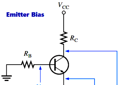
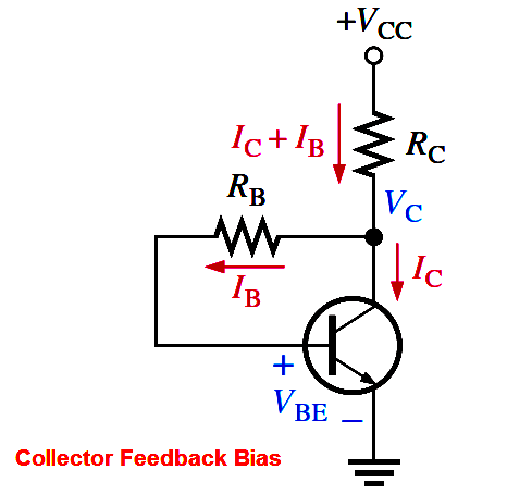
In Figure, the base resistor RB is connected to the collector rather than to VCC, as it was in the base bias arrangement discussed earlier. The collector voltage provides the bias for the base-emitter junction. The negative feedback creates an “offsetting” effect that tends to keep the Q-point stable. If IC tries to increase, it drops more voltage across RC, thereby causing VC to decrease. When VC decreases, there is a decrease in voltage across RB, which decreases IB. The decrease in IB produces less IC which, in turn, drops less voltage across RC and thus offsets the decrease in VC.

Analysis of a Collector-Feedback Bias Circuit 

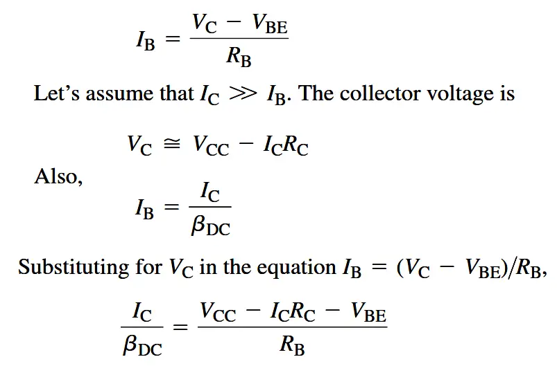
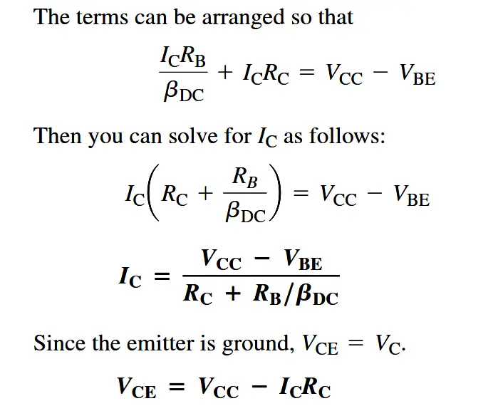
By Ohm’s law, the base current can be expressed as

Transistor-collector-feedback-bias-derivation.png

transistor_collector-feedback-bias-derivation


Q-Point Stability Over Temperature

Above Equation  shows that the collector current is dependent to some extent on βDC and VBE. This dependency, of course, can be minimized by making RC >> RB/βDC and VCC >> VBE. An important feature of collector-feedback bias is that it essentially eliminates the βDC and VBE dependency even if the stated conditions are met.

As you have learned, βDC varies directly with temperature, and VBE varies inversely with temperature. As the temperature goes up in a collector-feedback circuit, βDC goes up and VBE goes down. The increase in βDC acts to increase IC. The decrease in VBE acts to increase IB which, in turn also acts to increase IC. As IC tries to increase, the voltage drop across RC also tries to increase. This tends to reduce the collector voltage and therefore the voltage across RB, thus reducing IB and offsetting the attempted increase in IC and the attempted decrease in VC. The result is that the collector-feedback circuit maintains a relatively stable Q-point. The reverse action occurs when the temperature decreases.

Don't Miss Our Updates
Be the first to get exclusive content straight to your email.
We promise not to spam you. You can unsubscribe at any time.
Invalid email address
You've successfully subscribed !

Continue Reading

Transistor as an Amplifier in Common Emitter
How the Matrix Keypad works with a Micro controller?
Half Wave Voltage Doubler using Diodes
Basics of Ohm’s Law
Transistor Amplifier Working Principle
Phototransistor Working Principle
Share This Article
Facebook Whatsapp Whatsapp LinkedIn Copy Link
Share
Leave a Comment

Leave a Reply Cancel reply

Your email address will not be published. Required fields are marked *

Stay Connected

128.3kFollowersLike
69.1kFollowersFollow
210kSubscribersSubscribe
38kFollowersFollow

Categories

Explore More

Diodes Voltage Quadrupler
Voltage Divider Rule
Short Circuit and Open Circuit
Circuit Elements and Types of Circuits
Seven Segment Display Working Principle
Comparison of Half wave Rectifiers and Full wave Rectifiers
Zener Diode Limiter
Difference between Schottky Diode and PN junction Diode

Keep Learning

Why Silicon is preferred over Germanium ?

Why Silicon is preferred over Germanium ?

Electron Gun of CRT

Electron Gun of Cathode Ray Tube

diode-limiter-principle

Diode Limiters/Clippers Operation

reverse-biased varactor diode

Varactor Diode Operation

Diode Rectifier

Bridge Rectifier Working Animation

Dependent Voltage Source

Dependent Voltage Source

Diode-vi-characteristic-curve-for-forward-bias

VI Characteristic of a Diode

Tunnel Diode

Tunnel Diode Working Principle

Learn More

Ultrapure Water in the Semiconductor Industry

Ultrapure Water in the Semiconductor Industry

PLC Ladder Program for Automatic Car Wash

PLC Ladder Program for Automatic Car Wash using Siemens TIA Portal

limit-switch-works

How Limit Switch Works ?

Difference Between Squirrel Cage and Slip Ring Motors

Digital Electronics Multiple Choice Questions

Emitter-Coupled Logic (ECL) Objective Questions

What is a Fusible Loop System

What is a Fusible Plug? – Working, Advantages, Disadvantages

How to Filter Digital and Analog Inputs in a PLC

How to Filter Digital and Analog Inputs in a PLC?

PLC Automatic Pedal Switch for Speed Control

PLC Automatic Pedal Switch for Speed Control

Menu

  • About
  • Privacy Policy
  • Copyright

Quick Links

  • Learn PLC
  • Helping Hand
  • Part Time Job

YouTube Subscribe

Follow US
All rights reserved. Reproduction in whole or in part without written permission is prohibited.
Welcome Back!

Sign in to your account

Username or Email Address
Password

Lost your password?