Inst ToolsInst ToolsInst Tools
  • Courses
  • Automation
    • PLC
    • Control System
    • Safety System
    • Communication
    • Fire & Gas System
  • Instrumentation
    • Design
    • Pressure
    • Temperature
    • Flow
    • Level
    • Vibration
    • Analyzer
    • Control Valve
    • Switch
    • Calibration
    • Erection & Commissioning
  • Interview
    • Instrumentation
    • Electrical
    • Electronics
    • Practical
  • Q&A
    • Instrumentation
    • Control System
    • Electrical
    • Electronics
    • Analog Electronics
    • Digital Electronics
    • Power Electronics
    • Microprocessor
Search
  • Books
  • Software
  • Projects
  • Process
  • Tools
  • Basics
  • Formula
  • Power Plant
  • Root Cause Analysis
  • Electrical Basics
  • Animation
  • Standards
  • 4-20 mA Course
  • Siemens PLC Course
Reading: Bubble Tube Level Measurement Principle
Share
Notification Show More
Font ResizerAa
Inst ToolsInst Tools
Font ResizerAa
  • Courses
  • Design
  • PLC
  • Interview
  • Control System
Search
  • Courses
  • Automation
    • PLC
    • Control System
    • Safety System
    • Communication
    • Fire & Gas System
  • Instrumentation
    • Design
    • Pressure
    • Temperature
    • Flow
    • Level
    • Vibration
    • Analyzer
    • Control Valve
    • Switch
    • Calibration
    • Erection & Commissioning
  • Interview
    • Instrumentation
    • Electrical
    • Electronics
    • Practical
  • Q&A
    • Instrumentation
    • Control System
    • Electrical
    • Electronics
    • Analog Electronics
    • Digital Electronics
    • Power Electronics
    • Microprocessor
Follow US
All rights reserved. Reproduction in whole or in part without written permission is prohibited.
Inst Tools > Blog > Level Measurement > Bubble Tube Level Measurement Principle

Bubble Tube Level Measurement Principle

Last updated: August 13, 2018 11:19 pm
Editorial Staff
Level Measurement
3 Comments
Share
5 Min Read
SHARE

In the bubble type level system, liquid level is determined by measuring the pressure required to force a gas into a liquid at a point beneath the surface.

This method uses a source of clean air or gas and is connected through a restriction to a bubble tube immersed at a fixed depth into the vessel.  The restriction reduces the airflow to a very small amount. As the pressure builds, bubbles are released from the end of the bubble tube.

Pressure is maintained as air bubbles escape through the liquid.  Changes in the liquid level cause the air pressure in the bubble tube to vary. At the top of the bubble tube is where a pressure sensor detects differences in pressure as the level changes.

Most tubes use a small V-notch at the bottom to assist with the release of a constant stream of bubbles.   This is preferable for consistent measurement rather than intermittent large bubbles.

Bubble Tube Level measurement

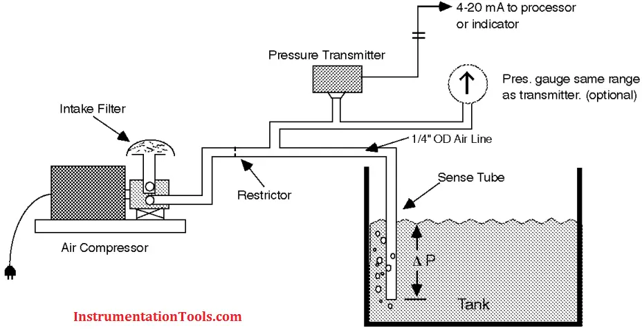
The Bubbler System is an inexpensive but accurate means of measuring the fluid level in open or vented containers, especially those in harsh environments such as cooling tower sumps, swimming pools, reservoirs, vented fuel tanks, drain sumps, air washers, etc. The system consists of a source of compressed air, air flow restrictor, sensing tube and pressure transmitter. The only component of the Bubbler System that is exposed to the elements is the sensing tube. All other components can be remotely located in a protected area.

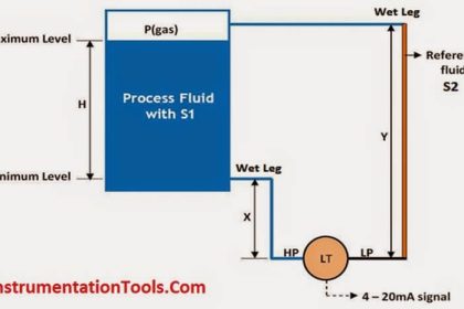
The sense tube is installed in the tank and connected to the pressure transmitter and the air supply through the flow restrictor as shown in Figure. Since the pressure required to displace the liquid is determined by the depth of the fluid, the transmitter output indicates the fluid depth above the open end of the sense tube.

Note that it is not necessary to extend the sense tube to the bottom of the container if you are only interested in the fluid height in the top part of the container. Using a shorter sense tube and lower range pressure transmitter will improve the resolution and accuracy of the system.

It may be necessary to install a check valve at the high point in the air line if the fluid level is above the air supply and pressure transmitter. This may prevent siphoning of the fluid back to the transmitter and air compressor if there is a power failure.

Principle:

Bubblers, are all hydrostatic measurement devices. This technology is used in vessels (tanks) that operate under atmospheric pressure.  A dip tube having its open end near the vessel bottom carries a purge gas (typically air, although an inert gas such as dry nitrogen may be used when there is danger of contamination of or an oxidative reaction with the process fluid) into the tank.

As gas flows down to the dip tube’s outlet, the pressure in the tube rises until it overcomes the hydrostatic pressure produced by the liquid level at the outlet. That pressure equals the process fluid’s density multiplied by its depth from the end of the dip tube to the surface and is monitored by a pressure transducer connected to the tube.

Advantages

  • Simple assembly
  • Suitable for use with corrosive fluids.
  • Intrinsically safe
  • High temp applications

Disadvantages

  • Requires compressed air and installation of air lines
  • Build-up of material on bubble tube not permissible
  • Not suited to pressurised vessels
  • Mechanical wear

Application Limitations

Bubble tube devices are susceptible to density variations, freezing and plugging or coating by the process fluid or debris.  The gas that is used can introduce unwanted materials into the process as it is purged.

Also the device must be capable of withstanding the maximum air pressure imposed if the pipe should become blocked. Rodding to clean the pipe is assisted by installing a tee section.

Also See: Bubble Level Measurement Animation

Don't Miss Our Updates
Be the first to get exclusive content straight to your email.
We promise not to spam you. You can unsubscribe at any time.
Invalid email address
You've successfully subscribed !

Continue Reading

The 5 ways Ultrasonic Sensors Work
Bubbler Liquid Level Transmitter Calculation
Guided Wave Radar Level Sensor Pressure and Temperature Effects
Capacitive Level Measurement
All About Instrumentation Impulse Lines
Types of Level Measurement
Share This Article
Facebook Whatsapp Whatsapp LinkedIn Copy Link
Share
3 Comments
  • sonu kumar sahani says:
    May 9, 2016 at 1:25 am

    sir I want to make the project of bubble tube level measurement.so please tell me about pressure transducer used in this details.

    Reply
  • Andrew says:
    March 19, 2020 at 1:20 pm

    thinking of building the system on the flotation scavenger cells. kindly assist by providing the necessary requirements.

    1. pressure transmitter measuring range
    2. 2 bubble tube lengths
    3. difference between the bubble tube lengths
    4. how do i incorporate slurry sg in configuring the transmitter

    this i want to build is a 2 bubbler tube system
    thank you

    Reply
  • Ajay singh says:
    July 26, 2021 at 8:08 pm

    Sir
    DP transmitter used in bubbler type level what are the limitations

    Reply

Leave a Reply Cancel reply

Your email address will not be published. Required fields are marked *

Stay Connected

128.3kFollowersLike
69.1kFollowersFollow
208kSubscribersSubscribe
38kFollowersFollow

Categories

Explore More

DP Transmitter Dry Leg & Wet Leg Calculations
Radar Tank Gauging
Types of Level Gauges
Servo Operated Float Level Measurement
Level Instruments General Specifications
Wrong Installation of Horn Type Radar Level Transmitter on Sloping Tank
Non-Contacting Radar Level Transmitter Working Principle
Hydrostatic Level Measurement

Keep Learning

Difference between Transparent Level Gauge and Reflex Level Gauge

Difference between Transparent Level Gauge and Reflex Level Gauge

Non‐contact RADAR Level Transmitter Pulse

Non Contact RADAR Level Transmitter Principle, Limitations, Design, Installation and Calibration

Probe Type Radar Level Transmitter

Contact Type Guided Wave Radar Level Transmitter Working Principle

RF Admittance Level Transmitter Working Principle

RF Admittance Level Transmitter Working Principle

Laser Level Measurement

Laser Level Measurement Principle

Guided Wave Radar Questions and Answers

Guided Wave Radar Questions and Answers

Level-Transmitters-Animation

Level Transmitter Animation

DP Diaphragm Capillary Seal Level instrument

DP Diaphragm Capillary Seal Level instrument Calibration Procedure

Learn More

Structured Text PLC Program for Measuring Event Duration

Structured Text PLC Program for Measuring Event Duration

Fieldbus Interview Questions

Interview Questions on Fieldbus Communication

Diodes Voltage Quadrupler

Diodes Voltage Quadrupler

How to Test a Pressure Gauge

How to Test a Pressure Gauge

Digital Output Card With Relay and Wet Contact

Wiring Diagrams of PLC and DCS Systems – DI, DO, AI, AO

Power Electronics Objective Questions

Power Diode Quiz

hand-crank megger photo

What is Megger Test?

pressure switches relay circuit

Determine the functions of Pressure Switches ?

Follow US
All rights reserved. Reproduction in whole or in part without written permission is prohibited.
Welcome Back!

Sign in to your account

Username or Email Address
Password

Lost your password?