Breather Valve, also known as direct acting Pressure/Vacuum Relief Valves, are special types of Relief Valves which are specifically designed for tank protection.
The range includes pressure only, vacuum only and combined Pressure/Vacuum Valves, all available with flanged outlets or vented to atmosphere.
Breather Valve
Pressure/Vacuum Relief Valves are used extensively on bulk storage tanks, including fixed roof tanks with floating covers, to minimize evaporation loss. The Valves prevent the build-up of excessive pressure or vacuum which can unbalance the system or damage the storage vessel.
Pressure and vacuum protection levels are controlled with weighted pallets or springs and can be combined to provide the required Pressure/Vacuum settings.
It is common to combine pallet and spring systems in one unit i.e. pressure settings require a spring section, whilst the vacuum settings use the pallet method.
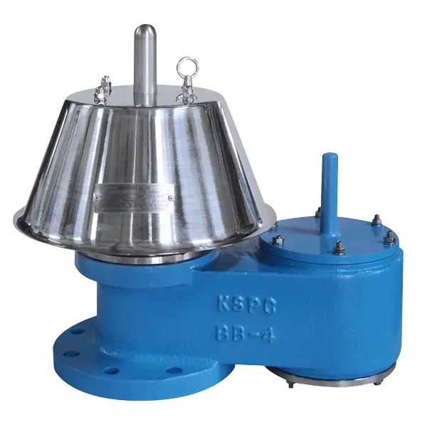
Why use Breather Valves?
The Breather Valve is a protection device mounted on a nozzle opening on the top of a fixed roof atmospheric storage tank. Its primary purpose is to protect the tank against rupturing or imploding.
Without an opening or a controlled opening, a fixed roof atmospheric tank would rupture under increasing pressure caused by pumping liquid into the tank or as a result of vapor pressure changes caused by severe thermal changes. Imploding, or the collapsing of a tank, occurs during the pumping out procedure or thermal changes.
As the liquid level lowers, the vapor space pressure is reduced to below atmospheric pressure. This vacuum condition must be alleviated through a controlled opening on the tank. In short, the tank needs to breathe in order to eliminate the possibility of rupturing or imploding.
Because of its primary function, this Valve is called Breather Valve. Valve selection should be in accordance with American Petroleum Institute Standard API 2000 or other applicable standard.
How do Breather Valves operate?
Most atmospheric tanks require a venting device that will allow large volumes of vapor to escape under relatively low pressures. Usually the allowable set pressure is in inches of water column pressure, both for positive and vacuum conditions.
This is because most large storage tanks have a relatively low maximum allowable working pressure. These tanks are generally large volume welded vessels that are built to API 650 standard. In order to accommodate large volumes at low set pressures, these Valves have ports that are greater in area than the inlet or nozzle connection.
The low setting required necessitates weight loading the Valve as opposed to spring loading. Because of the above, a Breather Valve requires approximately 100% over set pressure in order to reach full opening of the Valve.
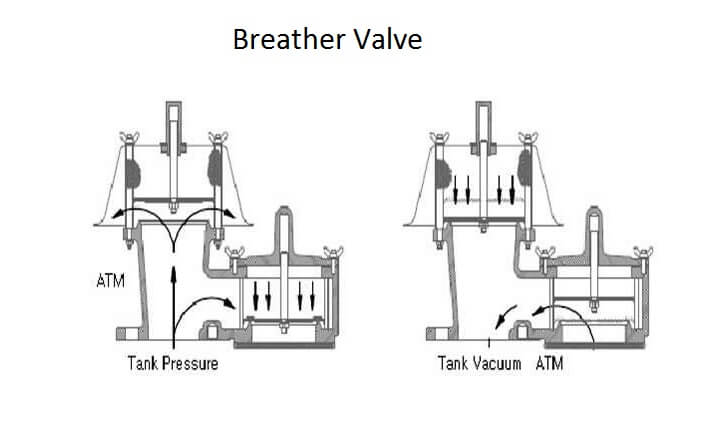
However, when deciding on a set pressure, the weight-loaded Valve operation MAWP should be at least twice the required set pressure to obtain optimum flow. If the MAWP is less than 100% above the required set, the Valve could be larger in size than normally required.
The possibility of Valve chatter and accelerated seat and diaphragm wear will exist if less than 20% over pressure is allowed. Simply stated, a Pressure/Vacuum Valve is not exactly like a high pressure safety Relief Valve and should not be sized at 10% or 20% over pressure.
When sizing a Pressure/Vacuum Valve, consult the manufacturer flow curves and allow sufficient overset pressure.
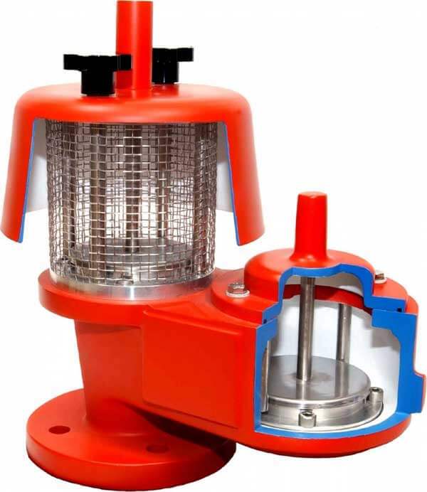
How Breather Valves Protect
How will Breather Valves protect the contents of a container from moisture intrusion? The answer to this question depends on five factors:
1. Pressure and Vacuum Settings
Breather Valves are made in a variety of settings, ranging from 0.2 psid to 5.0 psid or more. These settings, which are the points at which the valves seal, must be at least 1.0 psi to 1.5 psi below the pressure or vacuum which the container can safely withstand without leaking or deforming (see Selection below).
Generally speaking, the lower the valve setting, the more often the valve will open, admitting outside atmosphere and shortening the life of the desiccant.
2. Temperature Variations
The number of times a Breather Valve will open during storage depends not only on the valve setting, but also on the magnitude and frequency of temperature variations which may occur in a particular storage area. In sealed containers there is a pressure change ranging from 1.0 to 1.5 psi for each 30°F temperature change
Long-term tests, which have been run on containers at AGM’s plant in Tucson, Arizona, indicate that valves with sealing pressures of 0.25 psid will open almost every day, while valves set to reseal at 0.5 psid may open up to 150 times a year, and valves set for 1.0 psid rarely open during storage. (It should be noted that these tests were run on rigid wall containers, and that low-setting valves on plastic containers with flexible walls will probably not open as often under the same conditions.)
There are only a few locations in the world other than Tucson where greater diurnal temperature variations occur. Therefore, under worldwide storage conditions, valves with a 0.5 psid reseal in both directions will open no more than 200 times a year, and valves set for a 1.0 psid reseal in both directions will probably open less than a dozen times.
3. Temperature vs. Humidity
In addition to the number of times the Breather Valve opens, the amount of moisture taken into the container at each opening (or “gulp”) will determine desiccant life, and this is dependent on the climatic conditions of the storage area.
There are places in the world where as much as 0.015 grams of water per container cubic foot could be taken in at each “gulp.” (Reference NavWeps Report 8374, Table XII).
However, high humidity tends to limit temperature variations, so that even Breather Valves with very low settings will probably not open more than 2 or 3 times a year in these locations.
4. Number of Airlifts
For each descent from 10.7 psia (normal pressurization level in an aircraft cargo compartment) to 14.7 psia (sea level), a Breather Valve set for 0.5 psid reseal in both directions will take in approximately 0.013 grams of water per cubic foot of container volume.
Higher or lower valve settings will not substantially vary the amount of moisture gain per descent. Therefore, the amount of desiccant needed will, in part, depend on the number of airlifts anticipated.
5. Amount of Desiccant
It has been noted above that in ground storage, each time a container must breathe it will take in as much as 0.015 grams of water per cubic foot, and during each air descent in a pressurized cargo compartment it will take in as much as 0.013 grams of water per cubic foot.
Since MIL-STD-2073-I requires 1.2 units of desiccant per cubic foot in a sealed rigid metal container (plus additional amounts for dunnage, if any) and one unit of desiccant will hold 6.0 grams of water at 40% relative humidity (RH) at 77°F, this amount of desiccant will protect the container for a total of 480 “gulps” in ground storage, or a total of 550 airlifts, or some combination of the two.
Keeping the above factors in mind, we see that a Breather Valve, properly selected and used in conjunction with adequate desiccant, can provide years of moisture protection in a lightweight, low cost container.
Source : wermac & agmcontainer
Read Next:
- What is Mixing or Diverting Valve?
- PLC Control Valve Scaling
- Classification of Control Valves
- Pneumatic Valve Positioner
- What is a Disc Valve ?



Dear mr / mrs,
We are manufacturer of FRP tanks and accessoires. In case of closed tanks systems we normally use a gas scrubber with a vacuum breaker by mean of an ball construction. However the minimum opening pressure is 10 mbar or more. That means that the tanks should be designed for this openings pressure minimum.
But a better alternative is a breather valve. As far we know such valve can be adjusted as follows:
– External pressure (vacuum) e.g. 2, 3 or 4 mbarg or some like that.
– Internal pressure, e.g.+20 or +25 mbarg
Connection DN50 / 2″, with a preference for flanged connection.
Can you some data sheets and an price indication (+/- 15%).
We have to quote this week.
What are material to be executed?
– Aluminium with PTFE (or some thing like that) membrane?
– Do you an alternative in thermo plastic too?
Thanking in advance for your quick response
Dear Sir,
Kindly provide me with your quote for the procurement of Valve breather 7-T-1101 AKTEK TP1220M3.