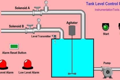
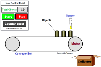
This article will discuss the system for filling liquids into Bottles using Omron PLC CX-Programmer. This PLC system is designed to automate the liquid filling process into bottles with a high level of accuracy and volume consistency. In this system, the bottles will be carried by a Conveyor, and when the bottles are in the filling area, the conveyor will stop for a moment to fill the liquid into the bottles. The conveyor will run again when the bottles are full. Bottles that have been filled with liquid will be counted by the system. When the system is Run in Auto mode, the system will stop when the number of bottles filled reaches the desired number.
Program Objective
- System Start: When the system is turned ON, the Conveyor will start running. The conveyor will carry Empty Bottles.
- Auto Mode: When the system is run in Auto mode, the Set Value parameter for the desired number of Bottles must be set.
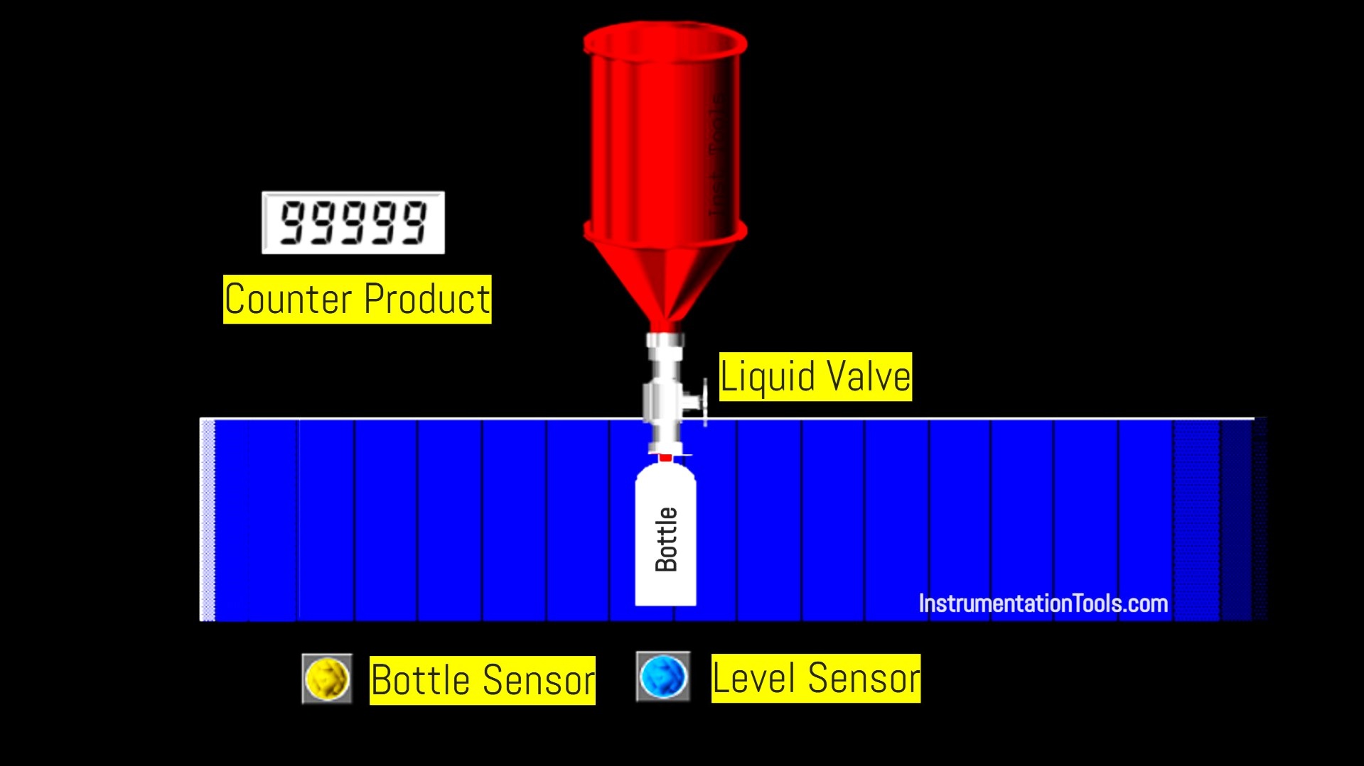
- Bottle Detection: The bottle sensor will detect Empty Bottles carried by the Conveyor.
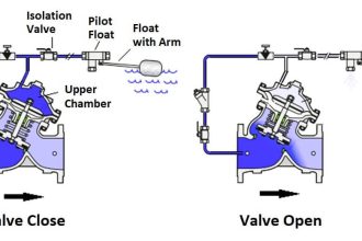
- Filling Process: If an Empty Bottle is detected, the system will open the solenoid valve to drain the liquid into the bottle. The liquid will flow into the Bottle until the level sensor detects that the Bottle is full.
- Stopping Filling: When the Bottle is full, the system will close the solenoid valve to stop the flow of liquid.
- The conveyor will run again, and the system will count the bottles that have been filled with liquid.
Bottle Filling Conveyor System
IO Mapping
| S.No. | Comment | Input (I) | Output (Q) | Memory Bits | Memory Word | Timer |
|---|---|---|---|---|---|---|
| 1 | START | 0.00 | ||||
| 2 | STOP | 0.01 | ||||
| 3 | SENS_BOTTLE | 0.02 | ||||
| 4 | SENS_LEVEL | 0.03 | ||||
| 5 | RESET_COUNTER | 0.04 | ||||
| 6 | SELECTOR_SWITCH | 0.05 | ||||
| 7 | CONVEYOR | 100.00 | ||||
| 8 | VALVE_LIQUID | 100.01 | ||||
| 9 | PV_COUNTER | D0 | ||||
| 10 | SV_COUNTER | D1 | ||||
| 11 | TIMER1 | T0000 | ||||
| 12 | SYSTEM_ON | W0.00 | ||||
| 13 | IR_CUTOFF | W0.01 |
Omron PLC Project
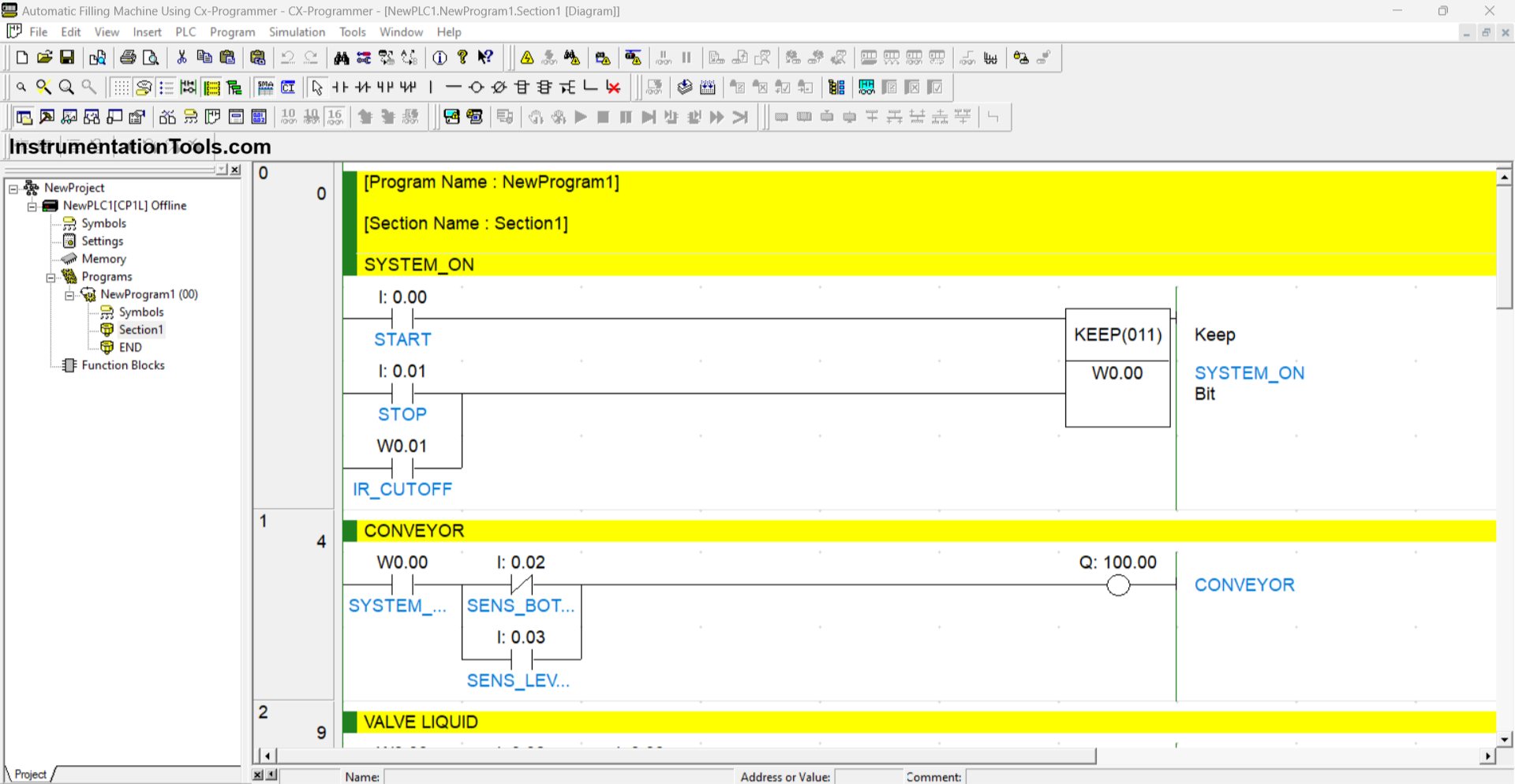
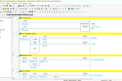
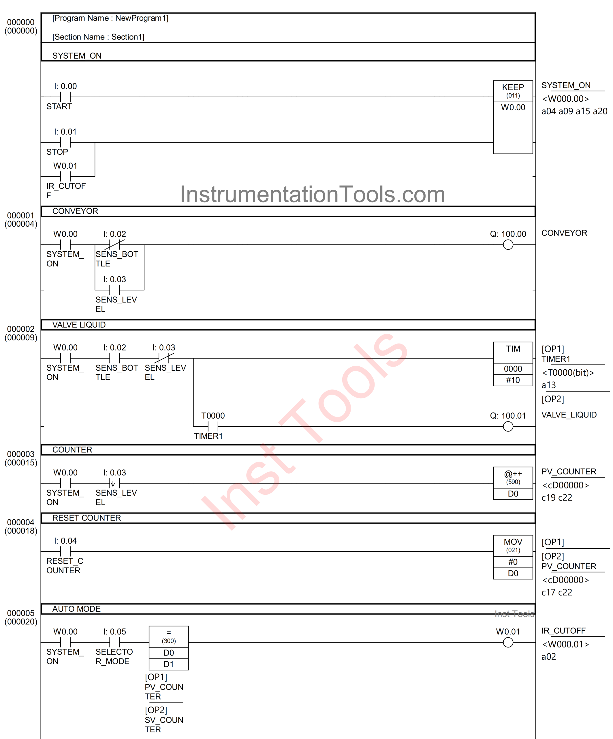
RUNG 0 (SYSTEM_ON)
In this Rung, when the START (0.00) button is Pressed, the memory bit SYSTEM_ON (W0.00) will be in the HIGH state. The memory bit SYSTEM_ON (W0.00) will remain in the HIGH state even though the button START (0.00) has been Released, because it uses the KEEP(011) instruction.
If the button STOP (0.01) is Pressed or the NO contact of the memory bit IR_CUTOFF (W0.01) in the HIGH state, then the memory bit SYSTEM_ON (W0.00) will be in the LOW state.
RUNG 1 (CONVEYOR)
In this Rung, when the NO contact of the memory bit SYSTEM_ON (W0.00) is in the HIGH state and the NC contact of Sensor SENS_BOTTLE (0.02) is in the LOW state, the output CONVEYOR (100.00) will be ON.
The output CONVEYOR (100.00) will be OFF if the NC contact of Sensor SENS_BOTTLE (0.02) is in the HIGH state.
The output CONVEYOR (100.00) will return ON when the NO contact of the memory bit SYSTEM_ON (W0.00) and the NO contact of Sensor SENS_LEVEL(0.03) are in the HIGH state.

RUNG 2 (VALVE LIQUID)
In this Rung, when the NO contact of the memory bit SYSTEM_ON (W0.00) and Sensor SENS_BOTTLE (0.02) are in the HIGH state, the timer TIMER1 (T0000) will start counting up to “2” seconds. After Timer TIMER1 (T0000) has finished counting, the output VALVE_LIQUID (100.01) will become OPEN.
When the NC contact of Sensor SENS_LEVEL (0.03) is in the HIGH state, the timer TIMER1 (T0000) will be OFF, and Output VALVE_LIQUID (100.01) will return to CLOSE.
RUNG 3 (COUNTER)
In this Rung, when the NO contact of the memory bit SYSTEM_ON (W0.00) and Sensor SENS_LEVEL (0.03) are in the HIGH state, the value in the memory word PV_COUNTER (D0) will increase (+1). Because it uses the @++(590) instruction.

RUNG 4 (RESET COUNTER)
In this rung, when the button RESET_COUNTER (0.04) is Pressed, the value in the memory word PV_COUNTER (D0) will be Reset to zero “0”, because it uses the MOV(021) instruction.
RUNG 5 (AUTO MODE)
In this Rung, when the NO contacts of memory bit SYSTEM_ON (W0.00) and SELECTOR_SWITCH (0.05) are in the HIGH state and the value in the memory word PV_COUNTER (D0) is Equal To SV_COUNTER (D1), then the memory bit IR_CUTOFF (W0.01) will be in the HIGH state.
Read Next:
- PLC Program for Paper Cutting by Length and Count
- How To Map Mitsubishi Analog Inputs on Weintek HMI?
- PLC Programming for Mixing 3 Raw Materials in 4 Tanks
- Turn ON Lamps Alternately for Set Cycles in PLC Program
- XG5000 PLC Example: Water Level-Based Pump Control