Inst ToolsInst ToolsInst Tools
  • Courses
  • Automation
    • PLC
    • Control System
    • Safety System
    • Communication
    • Fire & Gas System
  • Instrumentation
    • Design
    • Pressure
    • Temperature
    • Flow
    • Level
    • Vibration
    • Analyzer
    • Control Valve
    • Switch
    • Calibration
    • Erection & Commissioning
  • Interview
    • Instrumentation
    • Electrical
    • Electronics
    • Practical
  • Q&A
    • Instrumentation
    • Control System
    • Electrical
    • Electronics
    • Analog Electronics
    • Digital Electronics
    • Power Electronics
    • Microprocessor
  • Request
Search
  • Books
  • Software
  • Projects
  • Process
  • Tools
  • Basics
  • Formula
  • Power Plant
  • Root Cause Analysis
  • Electrical Basics
  • Animation
  • Standards
  • 4-20 mA Course
  • Siemens PLC Course
Reading: Boiler Drum Level Transmitter Calibration
Share
Font ResizerAa
Inst ToolsInst Tools
Font ResizerAa
  • Courses
  • Design
  • PLC
  • Interview
  • Control System
Search
  • Courses
  • Automation
    • PLC
    • Control System
    • Safety System
    • Communication
    • Fire & Gas System
  • Instrumentation
    • Design
    • Pressure
    • Temperature
    • Flow
    • Level
    • Vibration
    • Analyzer
    • Control Valve
    • Switch
    • Calibration
    • Erection & Commissioning
  • Interview
    • Instrumentation
    • Electrical
    • Electronics
    • Practical
  • Q&A
    • Instrumentation
    • Control System
    • Electrical
    • Electronics
    • Analog Electronics
    • Digital Electronics
    • Power Electronics
    • Microprocessor
  • Request
Follow US
All rights reserved. Reproduction in whole or in part without written permission is prohibited.
Inst Tools > Blog > Instrumentation Tools > Boiler Drum Level Transmitter Calibration

Boiler Drum Level Transmitter Calibration

Last updated: November 12, 2019 4:34 pm
Editorial Staff
Instrumentation Tools Level Measurement
13 Comments
Share
5 Min Read
SHARE

Steam Drum Level is both a critical and difficult measurement to make. Control of the water level in the drum must be precise. A water level that is too high can result in water carryover into the steam piping. A level that is too low can expose the generating tubes (down comers), preventing the water in the drum from cooling the furnace tubes, possibly damaging them.

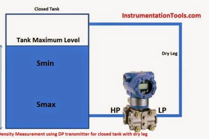
Measurement of boiler steam drum level using a differential pressure transmitter must take into account certain physical properties of the fluid.

1. The Steam drum contains a two-phase mixture of water and steam at saturation conditions.

2. The densities of water and steam vary with saturation temperature or pressure.

3. The density of saturated steam above water must be considered, as well as the density of saturated water in the drum.

Boiler Drum Level Transmitter calibrationBoiler Drum Level Transmitter calibration

This tool is used to calculate the Boiler Drum Level Transmitter calibration ranges.

The formulas used to calculate boiler drum level transmitter are:

At Hmin, The Transmitter output will be 4ma

∆Pmin or 4ma = [H(Ds-Do)+Hmin(Dw-Ds)] Do

At Hmax, The Transmitter output will be 20ma

∆Pmax or 20ma = [H(Ds-Do)+Hmax(Dw-Ds)] Do

Where,

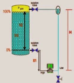
P0 = Static pressure in the steam drum at the top tap

Ds= Density of saturated steam at operating conditions

Dw = Density of saturated water at operating conditions

Do = Density of water in the “wet” or reference leg

H = Distance between the high and low drum taps

Hmax = Maximum water level allowed (measured from the bottom tap)

Hmin = Minimum water level allowed (measured from the bottom tap)

To perform the calibration, use a table of thermodynamic properties of steam and the following steps:

1. Determine hmin and hmax. These are the minimum and maximum water levels allowed for safe operation of the boiler. They are measured from the bottom tap of the steam drum.

2. Using the saturated steam tables, find the values of and at the drum operating pressure. Use the value for compressed water in the reference (wet) leg at the expected ambient temperature and the drum operating pressure. If the compressed water table is not available, use the reciprocal of the specific volume of saturated water at the ambient temperature. Since water is nearly incompressible, this provides reasonable accuracy for the drum measurement.

3. For this example assume:

The inside diameter of the steam drum is 60 in.

H = 33 in. (83.82 cm)

Po = 2,425 psig (design operating pressure)

Tambient = 105 °F (41 °C)

Hmin = 1.5 in. (3.81 cm)

Hmax = 31.5 in. (80.01 cm)

The desired level readout is –15 to 15 in. (a standard indicator faceplate range)

4. Solve the equation:

a. The specific volume of the saturated water at 2,425 psig is 0.02817 ft3/lb

Then Density of water is Dw = 1/specific volume of saturated water = 35.49 ft/lb3

b. The specific volume of the saturated steam at 2,425 psig is 0.1364 ft3/lb

Then Density of water is Dw = 1/specific volume of saturated water = 7.33 ft/lb3

c. The specific volume of the saturated water at 105 F temperature is 0.01615 ft3/lb

Then Density of water is Dw = 1/specific volume of saturated water = 61.93 ft/lb3

5. Now substitute all the values in the above formulas and calculate transmitter 4 ma and 20 ma equivalent DP ranges.

Finally, check the zero elevation and span against the transmitter specifications to ensure the selected transmitter can be calibrated to the required values

Don't Miss Our Updates
Be the first to get exclusive content straight to your email.
We promise not to spam you. You can unsubscribe at any time.
Invalid email address
You've successfully subscribed !

Continue Reading

Convert current (4-20mA) to Percentage (0-100%)
DP Flow Transmitter Re-Ranging Calculation
Practical Level Sensors Questions and Answers
What is Displacer Level Sensor ?
Density Measurement using DP Transmitter for closed tank with wet leg
How to Install Ultrasonic Level Transmitters
Share This Article
Facebook Whatsapp Whatsapp LinkedIn Copy Link
Share
13 Comments
  • Joseph says:
    April 20, 2015 at 5:17 pm

    Hi, I am used your tool to find out the transmitter ranges and working good. Thanks. Plz share more n more tools on Instrumentation.

    Reply
  • T Manikantan says:
    April 21, 2015 at 11:01 am

    You just converts a complex calculation to a simple calculation tool.

    Reply
  • B RadhaKrishna says:
    April 26, 2015 at 6:31 pm

    Thanks for sharing such a wonderful application.

    Reply
  • Ali says:
    May 14, 2015 at 11:00 am

    Amazing tools.

    Reply
  • Anonymous says:
    May 29, 2015 at 4:36 pm

    You have just created an wonderful application for our instrumentation engineers.

    Reply
  • Shaju says:
    August 14, 2015 at 5:34 am

    I have not worked on it. But it seems very comfortable calculations

    Reply
  • jayesh says:
    November 27, 2016 at 11:45 am

    please give information of drum level transmitter range

    Reply
  • adnaan says:
    February 19, 2017 at 9:06 am

    sir, how can loop check an ff transmitter, what is the output of ff transmitter, how can calibrate ff transmitter…

    Reply
  • RAMESH says:
    July 2, 2017 at 2:08 am

    Thanks very good information

    Reply
  • azetou says:
    July 3, 2017 at 6:53 am

    Great tool, thank you. by the way H is misrepresented in the drawing.

    Reply
  • Vinayak naik says:
    December 12, 2017 at 12:49 pm

    Thanks very good

    Reply
  • Ramkrishna says:
    December 19, 2017 at 4:50 am

    Thanks for giving such useful information.

    Reply
  • Khurram says:
    November 13, 2019 at 8:15 pm

    Please explain Boiler level reverse transmitter configuration.
    I.e transmiter high side connected to above and low side to below tapping of boiler.

    Reply

Leave a Reply Cancel reply

Your email address will not be published. Required fields are marked *

Stay Connected

128.3kFollowersLike
69.1kFollowersFollow
210kSubscribersSubscribe
38kFollowersFollow

Categories

Explore More

Questions on Level Switches
Level Sensors MCQ – Industrial Instrumentation
Open Tank Interface Level Measurement
Float Level Measurement
Effect of Temperature & Pressure on Level Measurement
What is Reflex Level Gauge?
RF Level Switches Working Principle
Advantages & Disadvantages of Level Measurement Systems

Keep Learning

torque tube displacement level transmitter

Level Troll working principle

Magnetic Level Indicator

Magnetic Level Indicator Principle, Limitations, Installation and Calibration

ultrasonic-level-measurement

Ultrasonic Level Transmitter Working Principle

Wet Leg Level Transmitter

Basics of DP Level Measurement

Hydrostatic pressure Measurement

Basics of Hydrostatic Level Measurement

Bubbler Liquid Level Transmitter Calculation

Bubbler Liquid Level Transmitter Calculation

Closed Tank Level Measurement Formula

Siemens Differential Pressure Transmitter Calculations (Flange Type)

RF-Capacitance Level Switch Principle

RF Capacitance Level Switch Working Principle

Learn More

PLC Logic for Stairway Lighting

Smart Automation Solutions: PLC Logic for Stairway Lighting

Voltage Control Methods at Distribution System

Factors affect Voltage Level Selection in Service System

Motors Inrush Currents

Motor Inrush Current Measurements

Polyphase Induction Motor Multiple Choice Questions and Answers

200+ Polyphase Induction Motor Multiple Choice Questions and Answers

Instrumentation Thread

Thread Sealant Types and Selection for Instrumentation Applications

how-to-avoid-bad-grounds

How to Avoid Bad Grounds ?

What is an HRC Fuse

What is an HRC Fuse? – Material, Types, Advantages

Programmable Logic Controller (PLC) Questions and Answers

Programmable Logic Controller (PLC) Questions and Answers – 3

Menu

  • About
  • Privacy Policy
  • Copyright

Quick Links

  • Learn PLC
  • Helping Hand
  • Part Time Job

YouTube Subscribe

Follow US
All rights reserved. Reproduction in whole or in part without written permission is prohibited.
Welcome Back!

Sign in to your account

Username or Email Address
Password

Lost your password?