In this article, you will learn about the boiler draught system, its types, purpose, definition, advantages, and disadvantages.
The small difference in pressure between outside cold atmospheric air and gases within a furnace or chimney is referred to as boiler draught.
The draught is required to force air through the fuel grate to aid in proper fuel combustion and to remove combustion products.
Fans are used to keep draughts at bay inside boilers.
Draught is defined as a small pressure difference between the fuel bed (furnace) and outside air required to maintain a constant flow of air and discharge gases to the atmosphere through the chimney.
Draughts can be produced by a chimney, a fan, a steam jet (or an air jet), or a combination of these.
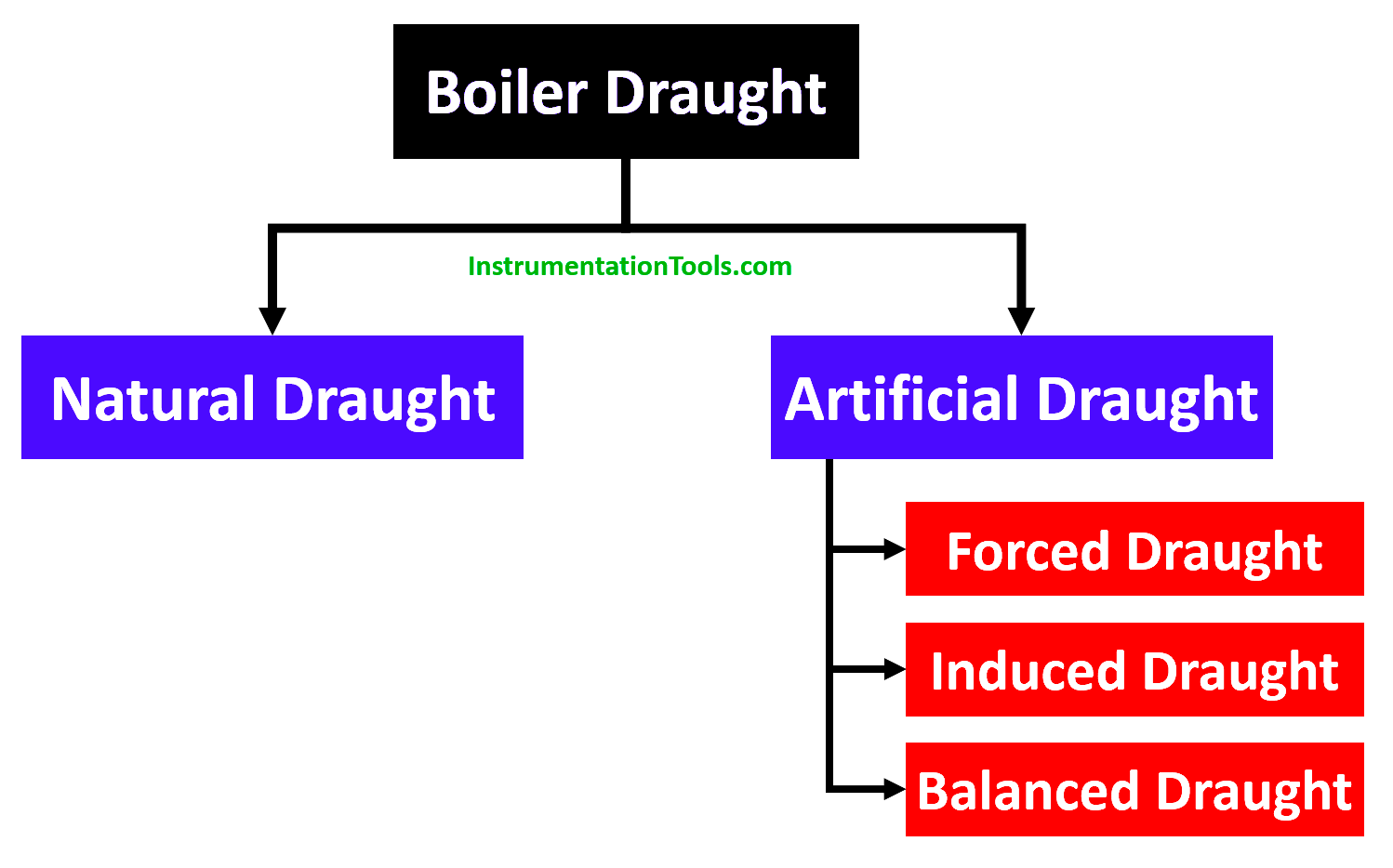
Boiler Draught is broadly classified into
In natural or chimney draught, the amount of draught is directly proportional to the height of the chimney. It is caused by the density difference between the hot gas column in the chimney and the cold air column outside the chimney.
To produce a significant amount of draught, the chimney height must be significantly increased, which is neither convenient nor economical.
Furthermore, because the draught is affected by climatic conditions, mechanical equipment is used to generate the required draught, and the draught so generated is referred to as artificial draught.
Artificial Draught is further classified as
A fan or blower is provided in a forced draught system, as shown in the figure, to force air into the combustion chamber. The combustion chamber is where air and fuel are burned and hot gases are produced.
After recovering heat from flue gases, these gases are forced to pass through the flue, economizer, and air pre-heater before being exhausted. Because the pressure of gases throughout the system is greater than atmospheric pressure, this draught system is known as a positive draught system.
It should be noted that the function of chimney use is to discharge gases high in the atmosphere in order to reduce air pollution, and it is not particularly important for producing draughts.
In the boiler system, this ID fan is located near a long vertical chimney. By lowering the pressure in the system below atmospheric pressure, the air is sucked into the system.
The flue gases produced by combustion are drawn through the system and, after recovering heat in the economizer and air-preheater, are exhausted to the atmosphere through the chimney.
It should be noted that the draught produced is unaffected by the temperature of hot gases, allowing the gases to be discharged as cold as possible after recovering as much heat as possible.
It is always preferable to use a combination of I.D. and F.D. rather than just Forced or Induced draught.
If only Forced Draught is used, the furnace cannot be opened for firing or inspection. Because the high-pressure air/gases inside the furnace will try to blow out, there is a good chance that the fire will be completely extinguished and the furnace will shut down.
If only an induced draught fan is used, the furnace cannot be opened for either firing or inspection. Because cold air will attempt to rush into the furnace, reducing the effective draught.
Balanced Draught is used to overcome both of these difficulties by I.D. and F.D. fans.
The temperature difference between hot gases in the chimney and cold atmospheric air outside the chimney causes a natural drought.
The advantages of natural draught are
The rate of draught produce s based upon:
The drought in modern power plants should be flexible to meet fluctuating loads and be independent of atmospheric conditions. To accomplish this, draught fans are required, and by using draught fans, the height of the chimney is reduced.
The blower (forced draught fan) in this system is located near the grate at the bottom of the boiler.
A forced fan forces air into the furnace, while an economizer and air preheater force flue gases into the chimney.
Because the fan is handling cold air, the fan size and power required are reduced. There is no need for water-cooled bearings because the air being handled is cold air.
The pressure in the Forced Draught system is high compared to the atmospheric pressure. Throughout the system, minimizing leakage of instrument air into the furnace.
A blower (induced draught fan) is located near (or at) the base of the chimney in an induced draught system. The fan draws flue gas from the furnace, creating a partial vacuum inside.
As a result, atmospheric air is forced through the furnace to aid in the combustion of fuel. The flue gases drawn by the fan are expelled into the atmosphere via the chimney.
When the furnace is opened for firing in an induced draught system, cold air enters and dilates the combustion. When the furnace is opened for firing in a forced draught system, the high-pressure air will try to blow out suddenly, causing the furnace to stop.
As a result, in both systems, the furnace cannot be opened for firing (q) inspection. To overcome the aforementioned difficulties, balanced draught, a combination of induced and forced draught, is used.
If you liked this article, then please subscribe to our YouTube Channel for Electrical, Electronics, Instrumentation, PLC, and SCADA video tutorials.
You can also follow us on Facebook and Twitter to receive daily updates.
Read Next:
PLC ladder logic design to control 3 motors with toggle switch and explain the program…
VFD simulator download: Master the online tool from the Yaskawa V1000 & programming software for…
The conveyor sorting machine is widely used in the packing industries using the PLC program…
Learn the example of flip-flop PLC program for lamps application using the ladder logic to…
In this article, you will learn the STAR DELTA programming using PLC controller to start…
Lube oil consoles of rotary equipment packages in industrial process plants are usually equipped with…


