Inst ToolsInst ToolsInst Tools
  • Courses
  • Automation
    • PLC
    • Control System
    • Safety System
    • Communication
    • Fire & Gas System
  • Instrumentation
    • Design
    • Pressure
    • Temperature
    • Flow
    • Level
    • Vibration
    • Analyzer
    • Control Valve
    • Switch
    • Calibration
    • Erection & Commissioning
  • Interview
    • Instrumentation
    • Electrical
    • Electronics
    • Practical
  • Q&A
    • Instrumentation
    • Control System
    • Electrical
    • Electronics
    • Analog Electronics
    • Digital Electronics
    • Power Electronics
    • Microprocessor
Search
  • Books
  • Software
  • Projects
  • Process
  • Tools
  • Basics
  • Formula
  • Power Plant
  • Root Cause Analysis
  • Electrical Basics
  • Animation
  • Standards
  • 4-20 mA Course
  • Siemens PLC Course
Reading: Basics of Permissive and Interlock Circuits
Share
Notification Show More
Font ResizerAa
Inst ToolsInst Tools
Font ResizerAa
  • Courses
  • Design
  • PLC
  • Interview
  • Control System
Search
  • Courses
  • Automation
    • PLC
    • Control System
    • Safety System
    • Communication
    • Fire & Gas System
  • Instrumentation
    • Design
    • Pressure
    • Temperature
    • Flow
    • Level
    • Vibration
    • Analyzer
    • Control Valve
    • Switch
    • Calibration
    • Erection & Commissioning
  • Interview
    • Instrumentation
    • Electrical
    • Electronics
    • Practical
  • Q&A
    • Instrumentation
    • Control System
    • Electrical
    • Electronics
    • Analog Electronics
    • Digital Electronics
    • Power Electronics
    • Microprocessor
Follow US
All rights reserved. Reproduction in whole or in part without written permission is prohibited.
Inst Tools > Blog > Instrumentation Design > Basics of Permissive and Interlock Circuits

Basics of Permissive and Interlock Circuits

Permissive and Interlock Circuits designed to interrupt a circuit if certain physical conditions are not met are called permissive contacts

Last updated: November 2, 2023 4:23 pm
Editorial Staff
Instrumentation Design PLC Tutorials
No Comments
Share
6 Min Read
SHARE

A practical application of switch and relay logic is in control systems where several process conditions have to be met before a piece of equipment is allowed to start.

Permissive and Interlock Circuits

A good example of this is burner control for large combustion furnaces.

In order for the burners in a large furnace to be started safely, the control system requests “permission” from several process switches, including high and low fuel pressure, air fan flow check, exhaust stack damper position, access door position, etc.

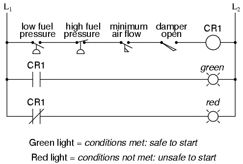
Each process condition is called a permissive, and each permissive switch contact is wired in series, so that if any one of them detects an unsafe condition, the circuit will be opened:
Basics of Permissive and Interlock Circuits

If all permissive conditions are met, CR1 will energize and the green lamp will be lit. In real life, more than just a green lamp would be energized:

usually a control relay or fuel valve solenoid would be placed in that rung of the circuit to be energized when all the permissive contacts were “good:” that is, all closed.

If any one of the permissive conditions are not met, the series string of switch contacts will be broken, CR2 will de-energize, and the red lamp will light.

Note that the high fuel pressure contact is normally-closed. This is because we want the switch contact to open if the fuel pressure gets too high. Since the “normal” condition of any pressure switch is when zero (low) pressure is being applied to it, and we want this switch to open with excessive (high) pressure, we must choose a switch that is closed in its normal state.

Another practical application of relay logic is in control systems where we want to ensure two incompatible events cannot occur at the same time.

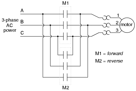
An example of this is in reversible motor control, where two motor contactors are wired to switch polarity (or phase sequence) to an electric motor, and we don’t want the forward and reverse contactors energized simultaneously:
Motor Interlock Circuits

When contactor M1 is energized, the 3 phases (A, B, and C) are connected directly to terminals 1, 2, and 3 of the motor, respectively.

However, when contactor M2 is energized, phases A and B are reversed, A going to motor terminal 2 and B going to motor terminal 1.

This reversal of phase wires results in the motor spinning the opposite direction. Let’s examine the control circuit for these two contactors:
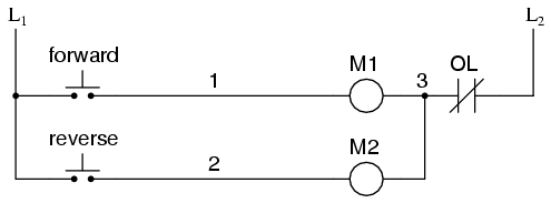
Motor Control Circuit using Relays

Take note of the normally-closed “OL” contact, which is the thermal overload contact activated by the “heater” elements wired in series with each phase of the AC motor.

If the heaters get too hot, the contact will change from its normal (closed) state to being open, which will prevent either contactor from energizing.

This control system will work fine, so long as no one pushes both buttons at the same time. If someone were to do that, phases A and B would be short-circuited together by virtue of the fact that contactor M1 sends phases A and B straight to the motor and contactor M2 reverses them; phase A would be shorted to phase B and vice versa. Obviously, this is a bad control system design!

To prevent this occurrence from happening, we can design the circuit so that the energization of one contactor prevents the energization of the other. This is called interlocking, and it is accomplished through the use of auxiliary contacts on each contactor, as such:
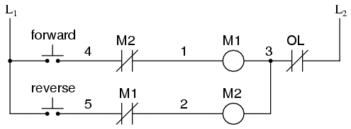
Motor Forward and Reverse Control Circuit

Now, when M1 is energized, the normally-closed auxiliary contact on the second rung will be open, thus preventing M2 from being energized, even if the “Reverse” pushbutton is actuated.

Likewise, M1‘s energization is prevented when M2 is energized. Note, as well, how additional wire numbers (4 and 5) were added to reflect the wiring changes.

It should be noted that this is not the only way to interlock contactors to prevent a short-circuit condition. Some contactors come equipped with the option of a mechanical interlock: a lever joining the armatures of two contactors together so that they are physically prevented from simultaneous closure.

For additional safety, electrical interlocks may still be used, and due to the simplicity of the circuit there is no good reason not to employ them in addition to mechanical interlocks.

Summary

  • Switch contacts installed in a rung of ladder logic designed to interrupt a circuit if certain physical conditions are not met are called permissive contacts, because the system requires permission from these inputs to activate.
  • Switch contacts designed to prevent a control system from taking two incompatible actions at once (such as powering an electric motor forward and backward simultaneously) are called interlocks.

If you liked this article, then please subscribe to our YouTube Channel for PLC and SCADA video tutorials.

You can also follow us on Facebook and Twitter to receive daily updates.

Read Next:

  • Basics of Fail-safe Circuits
  • Contacts and Coils in PLC
  • Pushbutton switches & Types
  • Piping &Instrumentation Drawing
Don't Miss Our Updates
Be the first to get exclusive content straight to your email.
We promise not to spam you. You can unsubscribe at any time.
Invalid email address
You've successfully subscribed !

Continue Reading

Define the Order of Execution in Functional Block Diagram of Studio 5000
Structured Text in PLC: Parking Information Systems
Waste-Burning System OMRON PLC Program Example
How to Export Data from WinCC Runtime Advanced into Excel using VB Script
OB1 – Main Cyclic Organization Block in TIA Portal
Types of Script in Intouch Scada
Share This Article
Facebook Whatsapp Whatsapp LinkedIn Copy Link
Share
Leave a Comment

Leave a Reply Cancel reply

Your email address will not be published. Required fields are marked *

Stay Connected

128.3kFollowersLike
69.1kFollowersFollow
210kSubscribersSubscribe
38kFollowersFollow

Categories

Explore More

How to Select a Fuse ?
Anti-static Wrist Straps in Industrial Automation
What is Loop Checking?
What is Complementary Split Range Control (CSRC)?
Count the Number of Cartons in a Storage Area PLC Logic
MCQ on PLC (Programmable Logic Controller)
Network Switch Requirement in SCADA and DCS Architecture
Siemens PLC Tia Portal – OB100 Start-up Organization Block

Keep Learning

How to Select a pH and ORP Meter

How to Select a pH or ORP Meter

Simatic 300 Station Configuration

Monitor and Modify Variables in Simatic Manager

Measuring Instruments

Flow Instruments – Selection, Principle & Application

PLC Programming Sequence Logic

PLC Programming to Control Lights in a Sequence

PLC Program Paint Spraying

PLC Program for Paint Spraying

Function and Application of FIFO Block

How to use FIFO Block in TIA Portal? – Siemens PLC Programming

Motor Feedback Fail Logic in PLC

Motor Feedback Fail Logic in PLC

Top Non-PLC Certification Courses for Automation Professionals

Top Non-PLC Certification Courses for Automation Professionals

Learn More

Electric Stress Control in Cables, Joints and Terminations

Electric Stress Control in Cables, Joints, and Terminations

Vacuum Circuit Breaker Principle

What is Vacuum Circuit Breaker?

Ohm Meter Circuit

Ohm Meter

How to Test a Transistor using Multimeter

How to Test a Transistor using Multimeter

HVAC Chiller

HVAC Valves

Single Phase Motor Manual Controller

Motor Controllers

OB and FB Blocks in Siemens PLC

Procedure for Siemens S7-300 Download from PC to PLC

Thermocouple Reference Junction

Thermocouple Working Principle

Menu

  • About
  • Privacy Policy
  • Copyright

Quick Links

  • Learn PLC
  • Helping Hand
  • Part Time Job

YouTube Subscribe

Follow US
All rights reserved. Reproduction in whole or in part without written permission is prohibited.
Welcome Back!

Sign in to your account

Username or Email Address
Password

Lost your password?