Logic circuits, whether comprised of electromechanical relays or solid-state gates, can be built in many different ways to perform the same functions. There is usually no one “correct” way to design a complex logic circuit, but there are usually ways that are better than others.
In control systems, safety is (or at least should be) an important design priority. If there are multiple ways in which a digital control circuit can be designed to perform a task, and one of those ways happens to hold certain advantages in safety over the others, then that design is the better one to choose.
Basics of Fail-safe Circuits
Let’s take a look at a simple system and consider how it might be implemented in relay logic. Suppose that a large laboratory or industrial building is to be equipped with a fire alarm system, activated by any one of several latching switches installed throughout the facility.
The system should work so that the alarm siren will energize if any one of the switches is actuated. At first glance it seems as though the relay logic should be incredibly simple: just use normally-open switch contacts and connect them all in parallel with each other:

Essentially, this is the OR logic function implemented with four switch inputs. We could expand this circuit to include any number of switch inputs, each new switch being added to the parallel network, but I’ll limit it to four in this example to keep things simple. At any rate, it is an elementary system and there seems to be little possibility of trouble.
Except in the event of a wiring failure, that is. The nature of electric circuits is such that “open” failures (open switch contacts, broken wire connections, open relay coils, blown fuses, etc.) are statistically more likely to occur than any other type of failure. With that in mind, it makes sense to engineer a circuit to be as tolerant as possible to such a failure.
Let’s suppose that a wire connection for Switch #2 were to fail open:

If this failure were to occur, the result would be that Switch #2 would no longer energize the siren if actuated.
This, obviously, is not good in a fire alarm system. Unless the system were regularly tested (a good idea anyway), no one would know there was a problem until someone tried to use that switch in an emergency.
What if the system were re-engineered so as to sound the alarm in the event of an open failure? That way, a failure in the wiring would result in a false alarm, a scenario much more preferable than that of having a switch silently fail and not function when needed.
In order to achieve this design goal, we would have to re-wire the switches so that an open contact sounded the alarm, rather than a closed contact.
That being the case, the switches will have to be normally-closed and in series with each other, powering a relay coil which then activates a normally-closed contact for the siren:

When all switches are unactuated (the regular operating state of this system), relay CR1 will be energized, thus keeping contact CR1 open, preventing the siren from being powered.
However, if any of the switches are actuated, relay CR1 will de-energize, closing contact CR1 and sounding the alarm. Also, if there is a break in the wiring anywhere in the top rung of the circuit, the alarm will sound.
When it is discovered that the alarm is false, the workers in the facility will know that something failed in the alarm system and that it needs to be repaired.
Granted, the circuit is more complex than it was before the addition of the control relay, and the system could still fail in the “silent” mode with a broken connection in the bottom rung, but its still a safer design than the original circuit, and thus preferable from the standpoint of safety.
This design of circuit is referred to as fail-safe, due to its intended design to default to the safest mode in the event of a common failure such as a broken connection in the switch wiring.
Fail-safe design always starts with an assumption as to the most likely kind of wiring or component failure, and then tries to configure things so that such a failure will cause the circuit to act in the safest way, the “safest way” being determined by the physical characteristics of the process.
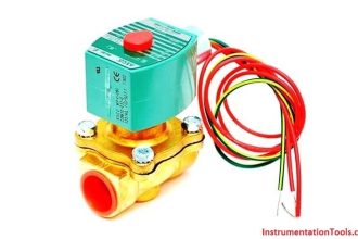
Take for example an electrically-actuated (solenoid) valve for turning on cooling water to a machine. Energizing the solenoid coil will move an armature which then either opens or closes the valve mechanism, depending on what kind of valve we specify. A spring will return the valve to its “normal” position when the solenoid is de-energized.
We already know that an open failure in the wiring or solenoid coil is more likely than a short or any other type of failure, so we should design this system to be in its safest mode with the solenoid de-energized.
If its cooling water we’re controlling with this valve, chances are it is safer to have the cooling water turn on in the event of a failure than to shut off, the consequences of a machine running without coolant usually being severe.
This means we should specify a valve that turns on (opens up) when de-energized and turns off (closes down) when energized. This may seem “backwards” to have the valve set up this way, but it will make for a safer system in the end.
Summary :
- The goal of fail-safe design is to make a control system as tolerant as possible to likely wiring or component failures.
- The most common type of wiring and component failure is an “open” circuit, or broken connection. Therefore, a fail-safe system should be designed to default to its safest mode of operation in the case of an open circuit.
Credits : Roger Hollingsworth
If you liked this article, then please subscribe to our YouTube Channel for PLC and SCADA video tutorials.
You can also follow us on Facebook and Twitter to receive daily updates.
Read Next:
Probability for a Safety System
What is Alarm Management System ?
Logic Gates in PLC Ladder Logic