Inst ToolsInst ToolsInst Tools
  • Courses
  • Automation
    • PLC
    • Control System
    • Safety System
    • Communication
    • Fire & Gas System
  • Instrumentation
    • Design
    • Pressure
    • Temperature
    • Flow
    • Level
    • Vibration
    • Analyzer
    • Control Valve
    • Switch
    • Calibration
    • Erection & Commissioning
  • Interview
    • Instrumentation
    • Electrical
    • Electronics
    • Practical
  • Q&A
    • Instrumentation
    • Control System
    • Electrical
    • Electronics
    • Analog Electronics
    • Digital Electronics
    • Power Electronics
    • Microprocessor
  • Request
Search
  • Books
  • Software
  • Projects
  • Process
  • Tools
  • Basics
  • Formula
  • Power Plant
  • Root Cause Analysis
  • Electrical Basics
  • Animation
  • Standards
  • 4-20 mA Course
  • Siemens PLC Course
Reading: Basics of Ground Loops
Share
Font ResizerAa
Inst ToolsInst Tools
Font ResizerAa
  • Courses
  • Design
  • PLC
  • Interview
  • Control System
Search
  • Courses
  • Automation
    • PLC
    • Control System
    • Safety System
    • Communication
    • Fire & Gas System
  • Instrumentation
    • Design
    • Pressure
    • Temperature
    • Flow
    • Level
    • Vibration
    • Analyzer
    • Control Valve
    • Switch
    • Calibration
    • Erection & Commissioning
  • Interview
    • Instrumentation
    • Electrical
    • Electronics
    • Practical
  • Q&A
    • Instrumentation
    • Control System
    • Electrical
    • Electronics
    • Analog Electronics
    • Digital Electronics
    • Power Electronics
    • Microprocessor
  • Request
Follow US
All rights reserved. Reproduction in whole or in part without written permission is prohibited.
Inst Tools > Blog > Erection & Commissioning > Basics of Ground Loops

Basics of Ground Loops

Last updated: September 4, 2019 7:27 am
Editorial Staff
Erection & Commissioning
1 Comment
Share
5 Min Read
SHARE

A ground loop is an undesirable current path in an electrical circuit. Ground loops occur whenever the ground conductor of an electrical system is connected to the ground plane at multiple points.

Contents
Causes of Ground LoopsImpedance Coupling (or Conductance Coupling)Inductive Coupling

Not only can ground loops induce noise in instrument signal cables, but in severe cases it can even overheat the instrument signal cable and thus present a fire hazard!

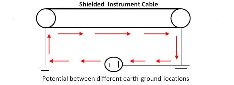
The phenomenon of ground loops is illustrated in the schematic diagram below:

Basics of Ground Loops

Causes of Ground Loops

There are several causes of ground loops in any instrumentation installation. Some of them are itemized below:

  • Differences in potential between the points of the ground plane to which the ground terminals have been connected.
  • Inductive coupling
  • Capacitive coupling
  • Use of internally grounded instruments inside an already grounded loop
  • Cable shields grounded at both ends
  • Grounded thermocouples with non-isolated transducers
  • Four wire transmitters used as input to a receiver instrument grounded to a different ground connection

There are several methods of curbing ground loops that introduces undesirable noise voltage into instrument signal cables.

However, two of the most effective methods of reducing ground loops are:

  • Single Point grounding
  • Use of Differential Inputs

Single point grounding involves grounding the instrumentation installation at a single point. This approach significantly reduces the noise voltage generated due to ground loops from multiple grounding points.

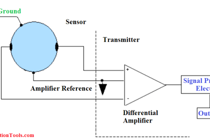
Differential inputs are used to cancel out the noise voltage that may appear in the instrumentation circuit.

One very effective way to completely isolate an instrumentation system from ground loops is to use battery powered instruments. However because of the limited life of a battery, they are seldom used.

Impedance Coupling (or Conductance Coupling)

Where two or more electrical circuits share common conductors, there can be some coupling between the different circuits.

When the signal current from one circuit proceeds back along the common conductor, it produces an error voltage along the return bus, which affects the other signals. The error voltage is due to the impedance in the return wire.

One way to reduce the effects of impedance coupling is to minimize the impedance of the return wire.

The second solution is to avoid any contact between the circuits and to use separate returns for each individual circuit.

Inductive Coupling

When a wire carries an electrical current it produces a magnetic field; if this wire is in the vicinity of another wire also carrying electrical current or signal, the magnetic field they produce interact with one another resulting in noise voltage being induced in the wires.

This is the principle through which inductive coupling takes place in instrumentation signal cable wiring

As we already know, Inductance is a property intrinsic to any conductor, whereby energy is stored in the magnetic field formed by current through the wire.

Mutual inductance existing between parallel wires forms a bridge. whereby an AC current through one wire is able to induce an AC voltage along the length of another wire.

This become even more pronounced if we have power cables and instrument signal cables going through the same duct or conduit.

A simple way to reduce inductive signal coupling is to simply separate conductors carrying incompatible signals.

This is why electrical power conductors and instrument signal cables are almost never found in the same conduit or in the same duct work together.

The most practical method of reducing inductive coupling and granting magnetic field immunity to instrument signal wires is to twist a pair of wires rather than allow them to lie along parallel straight lines. This greatly reduces the effects of electromagnetic induction.

Electromagnetic induction is reduced because when the wires are twisted so as to create a series of loops instead of one large loop, the inductive effects of the external magnetic field tend to cancel out thereby reducing the induced noise voltage on the instrument signal wires due to the external magnetic field.

Don't Miss Our Updates
Be the first to get exclusive content straight to your email.
We promise not to spam you. You can unsubscribe at any time.
Invalid email address
You've successfully subscribed !

Continue Reading

Installation and Calibration of Pressure Transmitter
P&ID Guidelines for Centrifugal Compressor Systems
DP Level Measurement Problems
Installation Precautions of Thermocouple and RTD
Pressure Transmitter Manifolds
What is Piping and Instrumentation Diagram (P&ID) ?
Share This Article
Facebook Whatsapp Whatsapp LinkedIn Copy Link
Share
1 Comment
  • Eduardo says:
    October 16, 2016 at 1:43 pm

    Very helpful!

    Reply

Leave a Reply Cancel reply

Your email address will not be published. Required fields are marked *

Stay Connected

128.3kFollowersLike
69.1kFollowersFollow
210kSubscribersSubscribe
38kFollowersFollow

Categories

Explore More

How to Install Ultrasonic Level Transmitters
Thermocouple Temperature Measurement Errors
Instrument Tube Fitting Installation – Part 2
Instrumentation Cables Armor
What are the Mounting Techniques of Diaphragm Seals?
Commissioning a Differential Pressure Transmitter in a Pressurized Boiler Steam Drum
Magnetic Float Level Switch Installation Techniques
Installation & Commissioning Tips for HART Devices

Keep Learning

cable-trays-glossary

Cable Trays Glossary

5-valve manifold

Pressure Transmitter Vent fittings

Cut-outs between Platforms or Grating for Field Instruments

Cut-outs between Platforms or Grating for Field Instruments

P&ID arrangement for Pressure Safety Valves

P&ID Guidelines for Pressure Safety Valves

How to Solve Cable Tray Sagging

How to Solve Cable Tray Sagging ?

Control Valves Pre-Commissioning Checklist

Control Valves Pre-Commissioning Checklist

Magnetic Flow Meters

Magnetic Flow Meters Installation Guidelines

P&ID Guidelines for Pumps Heat Exchangers

P&ID Guidelines for Pumps Heat Exchangers

Learn More

Power MOSFET Safe Operating Area

Power MOSFET Safe Operating Area

Conveyor and Puncher PLC Program

Toggle Switch & Sensor: Conveyor and Puncher PLC Program

hall effect speed sensor

Speed Probe Working Principle

Instrumentation Technical Interview Questions and Answers

Instrumentation Technical Interview Questions and Answers

Difference between HART and Foundation Fieldbus

Difference between HART and Foundation Fieldbus

What is calibration?

Why Silicon is preferred over Germanium ?

Why Silicon is preferred over Germanium ?

PLC Programming for Train Detection and Gate Operation

PLC Programming for Train Detection and Gate Operation

Menu

  • About
  • Privacy Policy
  • Copyright

Quick Links

  • Learn PLC
  • Helping Hand
  • Part Time Job

YouTube Subscribe

Follow US
All rights reserved. Reproduction in whole or in part without written permission is prohibited.
Welcome Back!

Sign in to your account

Username or Email Address
Password

Lost your password?