Inst ToolsInst ToolsInst Tools
  • Ask
  • Courses
  • Videos
  • Q & A
    • Interview
      • Instrumentation
      • Electronics
      • Electrical
      • Practical Questions
    • MCQ
      • Instrumentation MCQ
      • Electrical MCQ
      • Electronics MCQ
      • Control Systems MCQ
      • Analog Electronics MCQ
      • Digital Electronics MCQ
      • Power Electronics MCQ
      • Microprocessor MCQ
      • Multiple Choice Questions
  • EE
    • Electronics
      • Electronics Q & A
      • Electronic Basics
      • Electronic Devices & Circuits
      • Electronics Animation
      • Digital Electronics
    • Electrical
      • Electrical Basics
      • Electrical Q & A
      • Power Electronics
      • Electrical Machines
      • Electrical Animation
      • Power Systems
      • Switchgear & Protection
      • Transmission & Distribution
  • Measure
    • Control Valves
    • Calibration
    • Temperature
    • Pressure
    • Flow
    • Level
    • Analyzers
    • Switches
    • Vibration
    • Solenoid Valve
  • Control
    • PLC Tutorials
    • Control Systems
    • Safety Instrumented System (SIS)
    • Communication
    • Fire & Gas System
  • More
    • Design
    • Tools
    • Animation
    • Basics
    • Formulas
    • Standards
    • TextBooks
    • Common
    • Software
    • Excel Tools
    • Erection & Commissioning
    • Process Fundamentals
    • Videos
    • Books
Search
All rights reserved. Reproduction in whole or in part without written permission is prohibited.
Reading: Basic Transistor Amplifier Circuit Principle
Share
Notification Show More
Font ResizerAa
Inst ToolsInst Tools
Font ResizerAa
  • Courses
  • PLC Tutorials
  • Control Systems
Search
  • Ask
  • Courses
  • Videos
  • Q & A
    • Interview
    • MCQ
  • EE
    • Electronics
    • Electrical
  • Measure
    • Control Valves
    • Calibration
    • Temperature
    • Pressure
    • Flow
    • Level
    • Analyzers
    • Switches
    • Vibration
    • Solenoid Valve
  • Control
    • PLC Tutorials
    • Control Systems
    • Safety Instrumented System (SIS)
    • Communication
    • Fire & Gas System
  • More
    • Design
    • Tools
    • Animation
    • Basics
    • Formulas
    • Standards
    • TextBooks
    • Common
    • Software
    • Excel Tools
    • Erection & Commissioning
    • Process Fundamentals
    • Videos
    • Books
Follow US
All rights reserved. Reproduction in whole or in part without written permission is prohibited.
Inst Tools > Blog > Electronic Devices & Circuits > Basic Transistor Amplifier Circuit Principle

Basic Transistor Amplifier Circuit Principle

Last updated: September 27, 2016 2:22 pm
Editorial Staff
Electronic Devices & Circuits
No Comments
Share
3 Min Read
SHARE

A transistor amplifies current because the collector current is equal to the base current multiplied by the current gain, b. The base current in a transistor is very small compared to the collector and emitter currents. Because of this, the collector current is approximately equal to the emitter current.

With this in mind, let’s look at the circuit in Figure. An ac voltage, Vs, is superimposed on the dc bias voltage VBB by capacitive coupling as shown. The dc bias voltage VCC is connected to the collector through the collector resistor, RC.

Basic Transistor Amplifier Circuit Principle

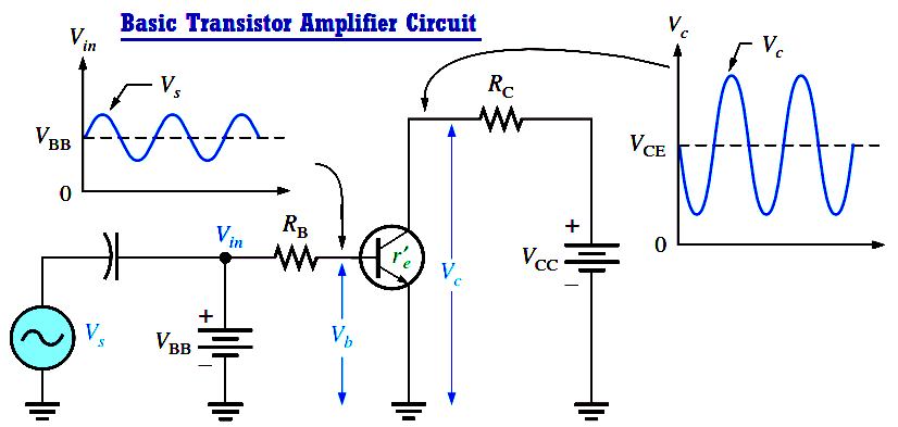
Fig : Basic transistor amplifier circuit with ac source voltage Vs and dc bias voltage VBB superimposed.

The ac input voltage produces an ac base current, which results in a much larger ac collector current. The ac collector current produces an ac voltage across RC, thus producing an amplified, but inverted, reproduction of the ac input voltage in the active region of operation, as illustrated in Above Figure.

The forward-biased base-emitter junction presents a very low resistance to the ac signal. This internal ac emitter resistance is designated re in Figure and appears in series with RB. The ac base voltage is

Vb = Ie.re

The ac collector voltage, Vc, equals the ac voltage drop across RC.

Vc = IcRC

Since Ic = Ie, the ac collector voltage is

Vc = IeRC

Vb can be considered the transistor ac input voltage where Vb = Vs – IbRB. Vc can be considered the transistor ac output voltage. Since voltage gain is defined as the ratio of the output voltage to the input voltage, the ratio of Vc to Vb is the ac voltage gain, Av, of the transistor.

Av = Vc / Vb

Substituting IeRC for Vc and Ie.re for Vb yields

basic-transistor-amplifier-gain-formula


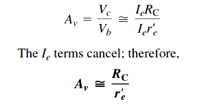
The above Equation shows that the transistor in Above Figure provides amplification in the form of voltage gain, which is dependent on the values of RC and re.

Since RC is always considerably larger in value than re , the output voltage for this configuration is greater than the input voltage.

Don't Miss Our Updates
Be the first to get exclusive content straight to your email.
We promise not to spam you. You can unsubscribe at any time.
Invalid email address
You've successfully subscribed !
Transistor as a Switch Working Principle
Difference between ideal diode & conventional diode
Dependent Current Source
N Type and P Type Semiconductors
Phototransistor Working Principle
Share This Article
Facebook Whatsapp Whatsapp LinkedIn Copy Link
Share
Leave a Comment

Leave a Reply Cancel reply

Your email address will not be published. Required fields are marked *

Stay Connected

128.3kFollowersLike
69.1kFollowersFollow
208kSubscribersSubscribe
38kFollowersFollow

Categories

Recent Comments

  • Guifty Shimica on Top Non-PLC Certification Courses for Automation Professionals
  • Guifty Shimica on Top Non-PLC Certification Courses for Automation Professionals
  • MIHARITSOA Aina Sitraka on Top Non-PLC Certification Courses for Automation Professionals
  • Vaishnavi on Free Instrumentation Course for Trainee Engineers

Related Articles

seven-segment-display-circuit

Seven Segment Display Working Principle

half-wave-voltage-doubler-using-diodes

Half Wave Voltage Doubler using Diodes

Transistor Amplifier Working Principle

Transistor as Amplifier

Transistor as Amplifier

transistor-terminals

Basics of Transistors

pn-junction-with-depletion-layer

How a PN Junction Formed in a Diode

half-wave-rectifier-working-animation

Half Wave Rectifier Principle

Combining Independent Voltage Sources in Series

Combining Independent Voltage Sources in Series

More Articles

factorytalk view studio hmi

How to Create Templates in FactoryTalk View Studio?

Capacitor and Symbols

Capacitance

Effects of Capillary Tubing on Pressure Measurement

Capillary Tubing Pressure Sensor Temperature & Elevation Problems

Shunt-Wound DC Generator Principle

Shunt-Wound DC Generators

Example of Automated Guided Vehicle with PLC

Example of Automated Guided Vehicle with PLC

Instrumentation Engineering Quiz

Instrumentation Engineering Quiz – Set 2

Redundant system communication cable

What is Interface Module in Siemens PLC?

Control Valve Whisper Trim Cage

Problem with Choked Control Valve with Whisper Trim Cage

Follow US
All rights reserved. Reproduction in whole or in part without written permission is prohibited.
Welcome Back!

Sign in to your account

Username or Email Address
Password

Lost your password?