Inst ToolsInst ToolsInst Tools
  • Courses
  • Automation
    • PLC
    • Control System
    • Safety System
    • Communication
    • Fire & Gas System
  • Instrumentation
    • Design
    • Pressure
    • Temperature
    • Flow
    • Level
    • Vibration
    • Analyzer
    • Control Valve
    • Switch
    • Calibration
    • Erection & Commissioning
  • Interview
    • Instrumentation
    • Electrical
    • Electronics
    • Practical
  • Q&A
    • Instrumentation
    • Control System
    • Electrical
    • Electronics
    • Analog Electronics
    • Digital Electronics
    • Power Electronics
    • Microprocessor
  • Request
Search
  • Books
  • Software
  • Projects
  • Process
  • Tools
  • Basics
  • Formula
  • Power Plant
  • Root Cause Analysis
  • Electrical Basics
  • Animation
  • Standards
  • 4-20 mA Course
  • Siemens PLC Course
Reading: Allen Bradley Powerflex VFD
Share
Font ResizerAa
Inst ToolsInst Tools
Font ResizerAa
  • Courses
  • Design
  • PLC
  • Interview
  • Control System
Search
  • Courses
  • Automation
    • PLC
    • Control System
    • Safety System
    • Communication
    • Fire & Gas System
  • Instrumentation
    • Design
    • Pressure
    • Temperature
    • Flow
    • Level
    • Vibration
    • Analyzer
    • Control Valve
    • Switch
    • Calibration
    • Erection & Commissioning
  • Interview
    • Instrumentation
    • Electrical
    • Electronics
    • Practical
  • Q&A
    • Instrumentation
    • Control System
    • Electrical
    • Electronics
    • Analog Electronics
    • Digital Electronics
    • Power Electronics
    • Microprocessor
  • Request
Follow US
All rights reserved. Reproduction in whole or in part without written permission is prohibited.
Inst Tools > Blog > PLC Tutorials > Allen Bradley Powerflex VFD

Allen Bradley Powerflex VFD

Last updated: March 4, 2021 12:12 pm
Editorial Staff
PLC Tutorials
No Comments
Share
6 Min Read
SHARE

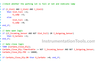
Getting started with Allen Bradley Powerflex VFD 

Contents
Allen Bradley Powerflex VFDSRC Control

To get started with Variable Frequency Drives, we have to know why industries are using VFD?.

As the name explains, the VFDs are used to vary the frequency of the AC wave they are receiving and send it to the output where an AC motor is wired.

So ultimately we are using VFD to control the speed of the AC motor.

We all have heard of Motor Control Center (MCC), they’re used to supply the power to motors and also used to start the motor in an efficient way with protection.

Now we might have a question whether I should have a separate control to start the motor when we use a VFD?

The answer is we don’t need a separate control when we use a VFD.

VFD provides the following advantages,

  • smooth starting
  • smooth acceleration & deceleration time
  • stopping methods
  • reversal of motor
  • reduce harmonics
  • increase power factor

Allen Bradley Powerflex VFD

Now that we understand why we prefer VFD. we are gonna jump on to how it is being used and few steps to control the speed of a motor using AB Powerflex 525 VFD.

This is the control diagram or wiring diagram of the Powerflex 525 VFD,

Allen Bradley Powerflex VFD

As you can see the terminals have specific names. Each terminal is used in a way to control the motor in different methods.

To get started we’re gonna see the simplest method to control an AC motor.

SRC Control

This method is called 2 Wire SRC Control – Non-Reversing

Now we’re gonna navigate on the display of the VFD and set the following parameters on it.

  1. P046 [Start Source] this is called the start source parameter. We’re gonna set the P046 to 2 in the VFD. Meaning we’re telling the VFD the external button is used to start the motor.
  2. T062 [DigIn TermBlk 02] we are gonna set this parameter to 48. Meaning we’re telling the VFD it is a 2-wire control.
  3. P045[Stop mode] this parameter is used to specify how to stop the motor. There are more than 4 modes to stop a motor. By default, this parameter is set to ‘0’ which means ‘ramp to stop’ meaning the motor will slowly stop when it is told to stop.
  4. P043 – This is the parameter where we can set the minimum frequency the VFD will output.
  5. P044 – This is the parameter where we can set the maximum frequency the VFD will output.
  6. P047 – This is the parameter where we tell the VFD to use this as a speed reference. Means, when I make a change to it, calculate accordingly and match the frequency output between a minimum and the maximum frequency which is given in parameters P044 and P043 and P044. In this case, I am gonna give it to ‘1’ which means the control is given to the potentiometer on the drive. When I rotate the potentiometer on the drive the frequency varies accordingly.

Now we’ve completed the programming part of the VFD. We’re going to wire it now.

VFD Stop Connections

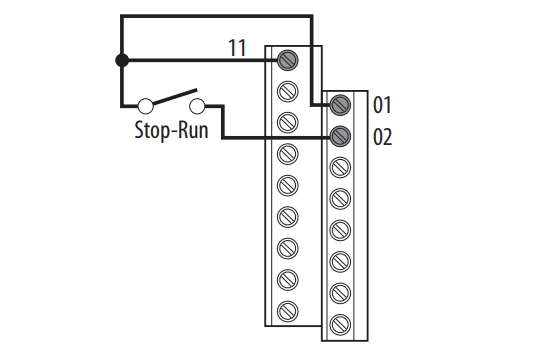
This is one way of wiring when we use the internal supply.

Terminal 11 is a 24v terminal and we’re wiring it to a NO switch and connecting the other end to the terminal two which acts as a source.

So when the switch is made to turn ‘ON’ the motor will start.

Terminal  ‘1’ is called an emergency stop and always a 24v supply is to be wired to it otherwise the VFD won’t give output.

When we cut the 24v while the motor is running the VFD recognizes it as an emergency situation and stops the motor and won’t work until it is made to start again after giving supply to the emergency stop.

Wiring External Supply in VFD

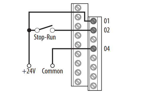
This is another way of wiring when we use an external supply.

Notice that we’re giving a ground connection to terminal 4 to complete the circuit.

We’ve learned the simplest way of designing and wiring the VFD to run an AC motor.

Author: Abishek D

If you liked this article, then please subscribe to our YouTube Channel for PLC and SCADA video tutorials.

You can also follow us on Facebook and Twitter to receive daily updates.

Read Next:

  • Variable Motor Speed Control
  • Motor ON OFF Logic in PLC
  • Troubleshooting Pump Control
  • VFD Working Principle
  • AC Motor Speed Control
Don't Miss Our Updates
Be the first to get exclusive content straight to your email.
We promise not to spam you. You can unsubscribe at any time.
Invalid email address
You've successfully subscribed !

Continue Reading

Explaining Various Types of Analog Instruments
Node-RED in PLC Industrial Automation
Wood Sawing and Blower System: PLC Control Design
PLC Programming using Level Switches
Structured Text vs. Instruction List for PLC Programming
PLC Program for Blinking Lamp on 5 Seconds Interval
Share This Article
Facebook Whatsapp Whatsapp LinkedIn Copy Link
Share
Leave a Comment

Leave a Reply Cancel reply

Your email address will not be published. Required fields are marked *

Stay Connected

128.3kFollowersLike
69.1kFollowersFollow
210kSubscribersSubscribe
38kFollowersFollow

Categories

Explore More

ICS System Design Considerations
Free Siemens PLC Training Course
PLC SCL Program for Marking Machine
Why is RTO used in the Place of TON Timer?
Create an Application in HMI using Tia Portal
Difference Between Normal Counters and Fast Counters – Learn PLC
What is a Tag? Types of Tags in SCADA
Package System Architecture – Control & Instrumentation

Keep Learning

PLC Program for Star Delta Starter using Functional Block Diagram

PLC Program for Star Delta Starter using Functional Block Diagram

Surface Grinding Process using PLC Program

Surface Grinding Process using PLC Program

PLC Program for Filling Operation

PLC Program for Continuous Filling Operation

Studio 5000 Define Program or Operator Control in Functional Block Diagram

Studio 5000: Define Program or Operator Control in Functional Block Diagram

Omron PLC Example

Design a Water Pump PLC Program using CX-Programmer

Parking Garage Indicator PLC Automation

Parking Garage Indicator: PLC Automation System

Function Block Programming in Studio 5000

Introduction to Functional Block Diagram in Studio 5000

Free Download SCADA Softwares

Free SCADA Software Download

Learn More

Differential Pressure Transmitter Manifold

Field Instrument Calibration Errors

Tap Changing Switch Animation

how-to-select-a-fuse

How to Select a Fuse ?

Online Analyzers Questions & Answers

Online Analyzers Questions & Answers

oxygen Safety Analyzer

Oxygen Safety Analyzer

ICS Control System

ICS Control System Security

Induced Draft Cooling Tower

Cooling Tower

PLC Memory Organization - Data Files and Program Files

PLC Memory Organization – Data Files and Program Files

Menu

  • About
  • Privacy Policy
  • Copyright

Quick Links

  • Learn PLC
  • Helping Hand
  • Part Time Job

YouTube Subscribe

Follow US
All rights reserved. Reproduction in whole or in part without written permission is prohibited.
Welcome Back!

Sign in to your account

Username or Email Address
Password

Lost your password?