To study the working of Allen Bradley Bitwise logical operations like AND, OR, NOT, XOR in Programmable logic Controllers (PLC).
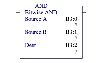
In the above picture, there are totally three parameters,
SOURCE A – Address of First Binary Value
SOURCE B – Address of Second Binary Value
DESTINATION –AND operation result of Source A & B stored in this address
In the above picture, there are totally three parameters,
SOURCE A –Address of First Binary Value
SOURCE B –Address of Second Binary Value
DESTINATION –OR operation result of Source A & B stored in this address
In the above picture, there are totally three parameters,
SOURCE A –Address of First Binary Value
SOURCE B –Address of Second Binary Value
DESTINATION –XOR operation result of Source A & B stored in this address
In the above picture, there are totally two parameters,
SOURCE -Address of Binary Value
DESTINATION –NOT operation result of Source stored in this address
When,
Source A : 0000 0000 0000 0000 (AND,OR & XOR)
Source B : 0000 0000 0000 0000 (AND,OR & XOR)
Source : 0000 0000 0000 0000 (NOT)
All Bitwise operator block are connected in parallel with input condition I: 0/0. When it goes ON, each block performs its operation. Since Source addresses are having zeros except NOT block remaining blocks are resulting 0s.
Source A : 0000 0000 0000 0000 (B3:0)
Source B : 0000 0000 0000 0000 (B3:1)
Destination : 0000 0000 0000 0000 (B3:2)
Source A : 0000 0000 0000 0000 (B3:0)
Source B : 0000 0000 0000 0000 (B3:1)
Destination : 0000 0000 0000 0000 (B3:3)
Source A : 0000 0000 0000 0000 (B3:0)
Source B : 0000 0000 0000 0000 (B3:1)
Destination : 0000 0000 0000 0000 (B3:4)
Source: 0000 0000 0000 0000 (B3:0)
Destination : 1111 1111 1111 1111 (B3:5)
When,
Source A : 0010 0101 0100 0001 (AND,OR & XOR)
Source B : 0001 0001 0001 0001 (AND,OR & XOR)
Source :0101 0100 1000 0111 (NOT)
I:0/0 giving input condition to all Bitwise Blocks. When it goes ON, value placed in Source A and Source B performs respective operation depends on blocks.
Source A : 0010 0101 0100 0001 (B3:0)
Source B : 0001 0001 0001 0001 (B3:1)
Destination : 0000 0001 0000 0001 (B3:2)
Source A : 0010 0101 0100 0001 (B3:0)
Source B : 0001 0001 0001 0001 (B3:1)
Destination : 0011 0101 0101 0001 (B3:3)
Source A : 0010 0101 0100 0001 (B3:0)
Source B : 0001 0001 0001 0001 (B3:1)
Destination : 0011 0100 0101 0000 (B3:4)
Source: 0101 0100 1000 0111 (B3:0)
Destination : 1010 1011 0111 1000 (B3:5)
We can use this explanation to understand the working of Bitwise logical operation like AND, OR, NOT, XOR in Allen Bradley Programmable logic Controllers (PLC).
If you liked this article, then please subscribe to our YouTube Channel for PLC and SCADA video tutorials.
You can also follow us on Facebook and Twitter to receive daily updates.
Read Next:
Ladder Logic using Toggle Switch
Learn the example of flip-flop PLC program for lamps application using the ladder logic to…
In this article, you will learn the STAR DELTA programming using PLC controller to start…
Lube oil consoles of rotary equipment packages in industrial process plants are usually equipped with…
Rotating equipment packages such as pumps, compressors, turbines need the lube oil consoles for their…
This article explains how to blink lights in ladder logic with a detailed explanation video…
In this article, a simple example will teach you the conversion from Boolean algebra to…


