Inst ToolsInst ToolsInst Tools
  • Courses
  • Automation
    • PLC
    • Control System
    • Safety System
    • Communication
    • Fire & Gas System
  • Instrumentation
    • Design
    • Pressure
    • Temperature
    • Flow
    • Level
    • Vibration
    • Analyzer
    • Control Valve
    • Switch
    • Calibration
    • Erection & Commissioning
  • Interview
    • Instrumentation
    • Electrical
    • Electronics
    • Practical
  • Q&A
    • Instrumentation
    • Control System
    • Electrical
    • Electronics
    • Analog Electronics
    • Digital Electronics
    • Power Electronics
    • Microprocessor
Search
  • Books
  • Software
  • Projects
  • Process
  • Tools
  • Basics
  • Formula
  • Power Plant
  • Root Cause Analysis
  • Electrical Basics
  • Animation
  • Standards
  • 4-20 mA Course
  • Siemens PLC Course
Reading: AC Generator Theory
Share
Notification Show More
Font ResizerAa
Inst ToolsInst Tools
Font ResizerAa
  • Courses
  • Design
  • PLC
  • Interview
  • Control System
Search
  • Courses
  • Automation
    • PLC
    • Control System
    • Safety System
    • Communication
    • Fire & Gas System
  • Instrumentation
    • Design
    • Pressure
    • Temperature
    • Flow
    • Level
    • Vibration
    • Analyzer
    • Control Valve
    • Switch
    • Calibration
    • Erection & Commissioning
  • Interview
    • Instrumentation
    • Electrical
    • Electronics
    • Practical
  • Q&A
    • Instrumentation
    • Control System
    • Electrical
    • Electronics
    • Analog Electronics
    • Digital Electronics
    • Power Electronics
    • Microprocessor
Follow US
All rights reserved. Reproduction in whole or in part without written permission is prohibited.
Inst Tools > Blog > Electrical Theory > AC Generator Theory

AC Generator Theory

Last updated: August 3, 2018 2:33 pm
Editorial Staff
Electrical Theory
No Comments
Share
2 Min Read
SHARE

AC generators are widely used to produce AC voltage. To understand how these generators operate, the basic theory of operation must first be understood.

Theory of Operation

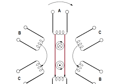
A simple AC generator consists of:

(a) a strong magnetic field,

(b) conductors that rotate through that magnetic field, and

(c) a means by which a continuous connection is provided to the conductors as they are rotating (Figure 3).

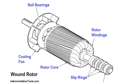
The strong magnetic field is produced by a current flow through the field coil of the rotor. The field coil in the rotor receives excitation through the use of slip rings and brushes. Two brushes are spring-held in contact with the slip rings to provide the continuous connection between the field coil and the external excitation circuit.

The armature is contained within the windings of the stator and is connected to the output. Each time the rotor makes one complete revolution, one complete cycle of AC is developed. A generator has many turns of wire wound into the slots of the rotor.

AC Generator Operation

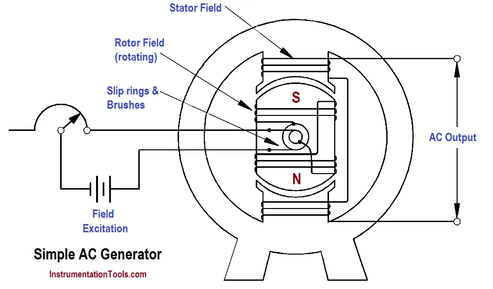
Figure 3 : Simple AC Generator

The magnitude of AC voltage generated by an AC generator is dependent on the field strength and speed of the rotor. Most generators are operated at a constant speed; therefore, the generated voltage depends on field excitation, or strength.

The frequency of the generated voltage is dependent on the number of field poles and the speed at which the generator is operated, as indicated in below Equation.
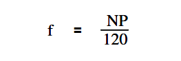
AC Generator Frequency Equation - 1

where

f = frequency (Hz)
P = total number of poles
N = rotor speed (rpm)
120 = conversion from minutes to seconds and from poles to pole pairs

The 120 in above Equation is derived by multiplying the following conversion factors.

AC Generator Frequency Equation - 2

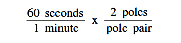
In this manner, the units of frequency (hertz or cycles/sec.) are derived.

Don't Miss Our Updates
Be the first to get exclusive content straight to your email.
We promise not to spam you. You can unsubscribe at any time.
Invalid email address
You've successfully subscribed !

Continue Reading

Three Phase Wattmeter
Single Line Diagram
AC Generation
3-Wire, Three-Phase Delta Wiring System
DC Machines Terminology
Single Phase AC Induction Motors
Share This Article
Facebook Whatsapp Whatsapp LinkedIn Copy Link
Share
Leave a Comment

Leave a Reply Cancel reply

Your email address will not be published. Required fields are marked *

Stay Connected

128.3kFollowersLike
69.1kFollowersFollow
208kSubscribersSubscribe
38kFollowersFollow

Categories

Explore More

Voltage Polarity and Current Direction
Y and Delta Resistor Network Calculations
Calculate Power in Parallel RL Circuit
Current Division
Compound Generators
Inductance and Inductive Reactance
Applying Kirchhoff’s Current Law
Ampere Hour Meter

Keep Learning

Megger Circuit Diagram

Multimeter & Megger Principle

Parallel Open Circuit Fault

Parallel Open Circuit Faults

Properties of Conducting Materials

Resistivity

DC Generator

DC Generator

Battery Hazard

Battery Hazards

Calculate Power in Parallel RC Circuit

Calculate Power in Parallel RC Circuit

DC Machine

DC Machines Construction

Electrical Symbols

Electrical Symbols

Learn More

thermocouple Transmitter Formula

Calculate Process Temperature using a Thermocouple

Difference Between Metering CT and Protection CT

Difference Between Metering CT and Protection CT

Thermowell-Insertion-and-Immersion-Length

What is a Transformer Tap Changer

Liquefied Petroleum Gas (LPG)

Properties of Liquefied Petroleum Gas (LPG)

Thermal Mass Flowmeter Principle

Thermal Mass Flow Meter – Principle, Advantages, Applications

PLC Program for Daily Production Record

PLC Program for Daily Production Record

Microsoft MS-200 certification

Best Preparation Tool You Can Get Online for Microsoft MS-200

Ethernet Switch Animation

Ethernet Bus Animation

Follow US
All rights reserved. Reproduction in whole or in part without written permission is prohibited.
Welcome Back!

Sign in to your account

Username or Email Address
Password

Lost your password?