This article discusses the implementation of an automatic bottle quality inspection system using a vision sensor and the TIA Portal. This system is designed to check bottle quality using a vision sensor. The inspection process is carried out for 4 seconds after the system detects the presence of a bottle; then the bottle is pushed onto the conveyor line using an Actuator. Based on the checking results, the system will classify bottles into two categories, namely bottles with Good quality and bottles with Bad quality. Bottle sorting is done by changing the bottle delivery route on the conveyor using an actuator. The actuator will direct the bottle to a storage container that matches its quality category. This system will also count the number of bottles that have been selected.
Program Objective
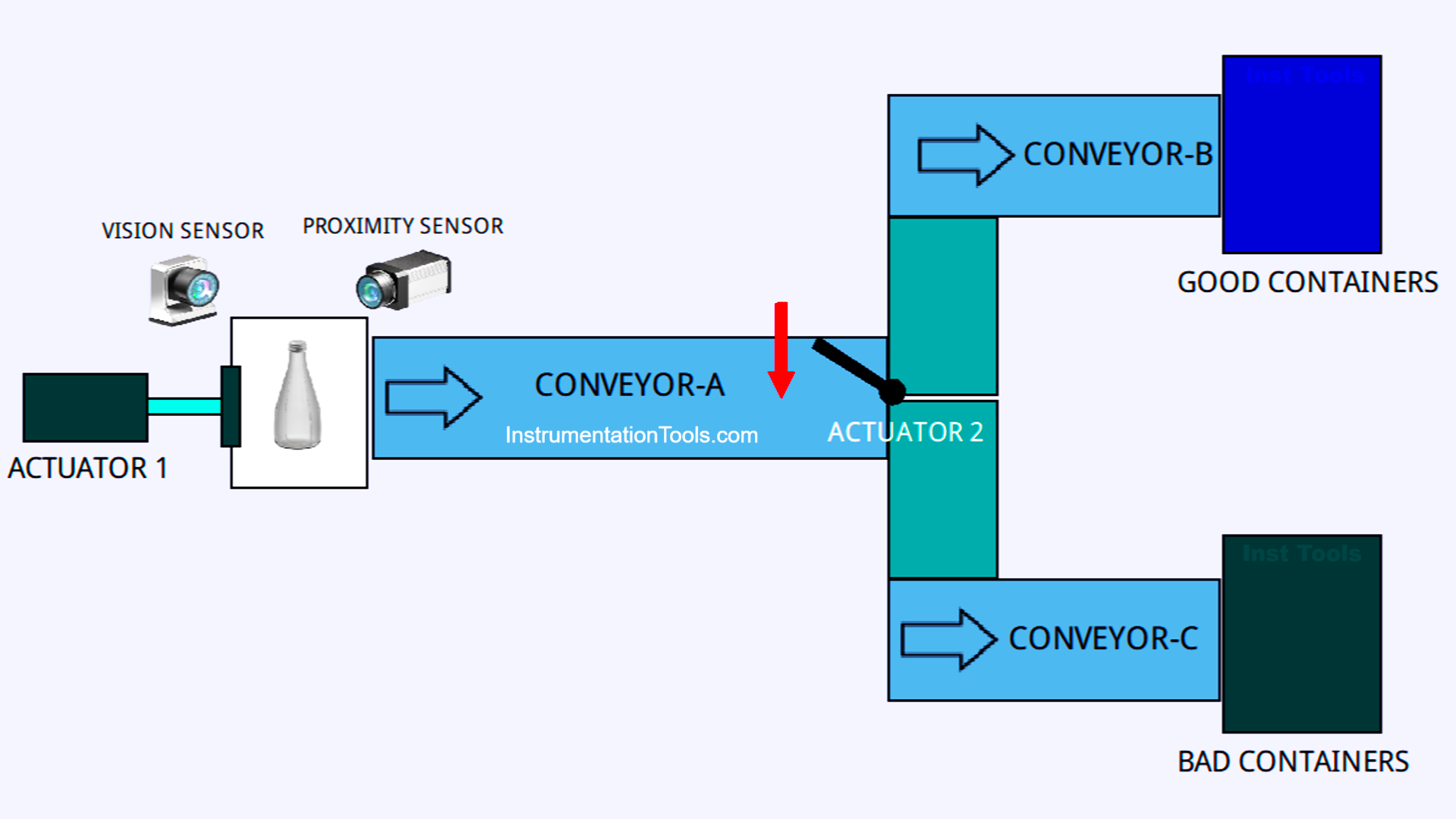
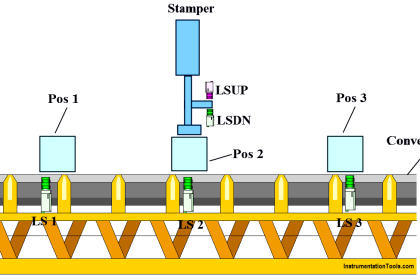
Sequence of Bottle Checking System
Starting the System:
When the system is turned on, all components are in standby condition.
Bottle Detection:
- Proximity sensor detects the presence of the bottle.
- Conveyor-A and Conveyor-C start running.
- The system provides a 4-second delay for the vision sensor to check the quality of the bottle.
- Actuator-1 pushes the bottles onto the track of Conveyor-A.
Bottle Quality Inspection:
a. Good Quality Bottles:
- Actuator-2 is Active and directs the bottles to the Conveyor-B track.
- Conveyor-B carries the bottles to a good-quality bottle container.
b. Bad Quality Bottles:
- Actuator-2 is Not Active, so the bottle remains on the Conveyor-C track.
- Conveyor-C carries the bottles to the Bad quality bottle container.
System Termination:
- After the bottle enters the holding container, all conveyors stop.
- The system counts the number of bottles processed.
Data Reset:
Bottle counter data can be reset by pressing the “Reset” button.
TIA Portal Exercise Mapping Details
| S.No. | Comment | Input (I) | Output (Q) | Memory Bit | Memory Word | Timer |
|---|---|---|---|---|---|---|
| 1 | START | I0.0 | ||||
| 2 | STOP | I0.1 | ||||
| 3 | PROXIMITY_SENS | I0.2 | ||||
| 4 | VISION_SENS | I0.3 | ||||
| 5 | LS_ACTUATOR_1 | I0.4 | ||||
| 6 | BOTTLE_GOOD_SENS | I0.5 | ||||
| 7 | BOTTLE_BAD_SENS | I0.6 | ||||
| 8 | RESET_COUNTER | I0.7 | ||||
| 9 | ACTUATOR_1 | Q0.0 | ||||
| 10 | ACTUATOR_2 | Q0.1 | ||||
| 11 | CONVEYOR_A | Q0.2 | ||||
| 12 | CONVEYOR_B | Q0.3 | ||||
| 13 | CONVEYOR_C | Q0.4 | ||||
| 14 | COUNTER_BOTTLE_BAD | MW1 | ||||
| 15 | COUNTER_BOTTLE_GOOD | MW0 | ||||
| 16 | TIMER1 | DB1 | ||||
| 17 | SYSTEM_ON | M2.0 | ||||
| 18 | IR_TIMER | M2.1 | ||||
| 19 | IR_LS_ACTUATOR_1 | M2.2 | ||||
| 20 | IR_VISION_SENS | M2.3 | ||||
| 21 | IR_BOTTLE_GOOD_SENS | M2.4 | ||||
| 22 | IR_BOTTLE_BAD_SENS | M2.5 |
Bottle Quality Inspection Using Vision Sensor
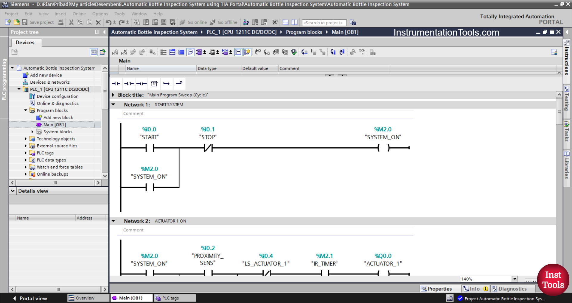
NETWORK 1 (START SYSTEM)
In this Network, when the START (I0.0) button is pressed, the memory bit SYSTEM_ON (M2.0) will be in the HIGH state. Even though the START (I0.0) button has been released, the memory bit SYSTEM_ON (M2.0) will remain in the HIGH state. Because it uses Latching.
If the STOP (I0.1) button is pressed, the memory bit SYSTEM_ON (M2.0) will be in the LOW state.
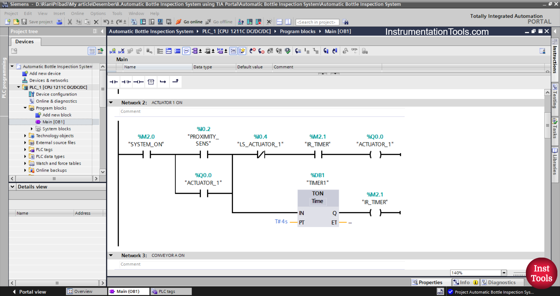
NETWORK 2 (ACTUATOR 1 ON)
In this Network, Timer TIMER1 (DB1) will start counting when the NO contact of the memory bit SYSTEM_ON (M2.0) and PROXIMITY_SENS(I0.2) sensor are in the HIGH state.
Timer TIMER1 (DB1) will count up to 4 seconds, and after it has finished counting, the output ACTUATOR_1 (Q0.0) will be ON. Even though the NO contact of the PROXIMITY_SENS (I0.2) sensor is in the LOW state, the ACTUATOR_1 (Q0.0) output will remain ON. Because it uses Latching.
If the NC contact of the limit switch LS_ACTUATOR_1 (I0.4) changes to the HIGH state, then the output ACTUATOR_1 (Q0.0) will be OFF.
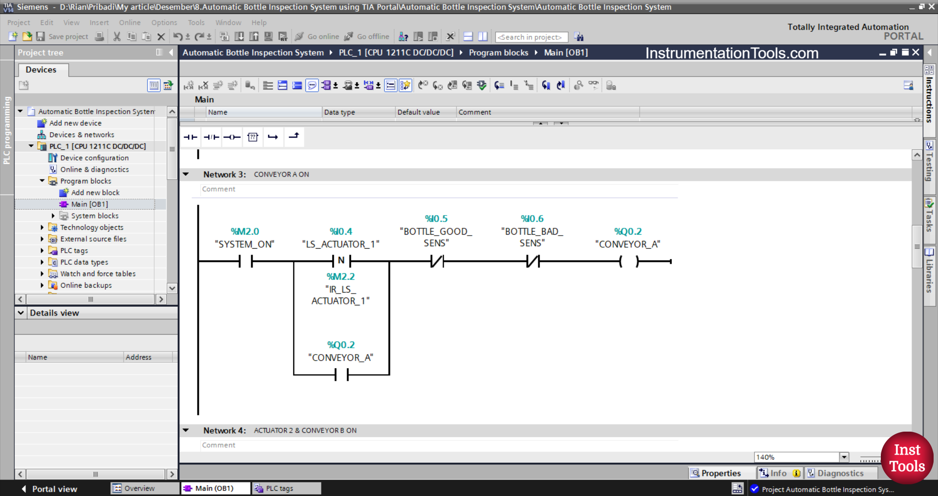
NETWORK 3 (CONVEYOR A ON)
In this Network, the output CONVEYOR_A (Q0.2) will be ON if the NO contact of the memory bit SYSTEM_ON (M2.0) and the limit switch LS_ACTUATOR_1 (I0.4) are in the HIGH state. Even though the NO contact of the limit switch LS_ACTUATOR_1 (I0.4) is in the LOW state, the CONVEYOR_A (Q0.2) output will remain ON. Because it uses Latching.
When the NC contact of the BOTTLE_GOOD_SENS (I0.5) and BOTTLE_BAD_SENS (I0.6) sensors is in the HIGH state, the CONVEYOR_A (Q0.2) output will return OFF.
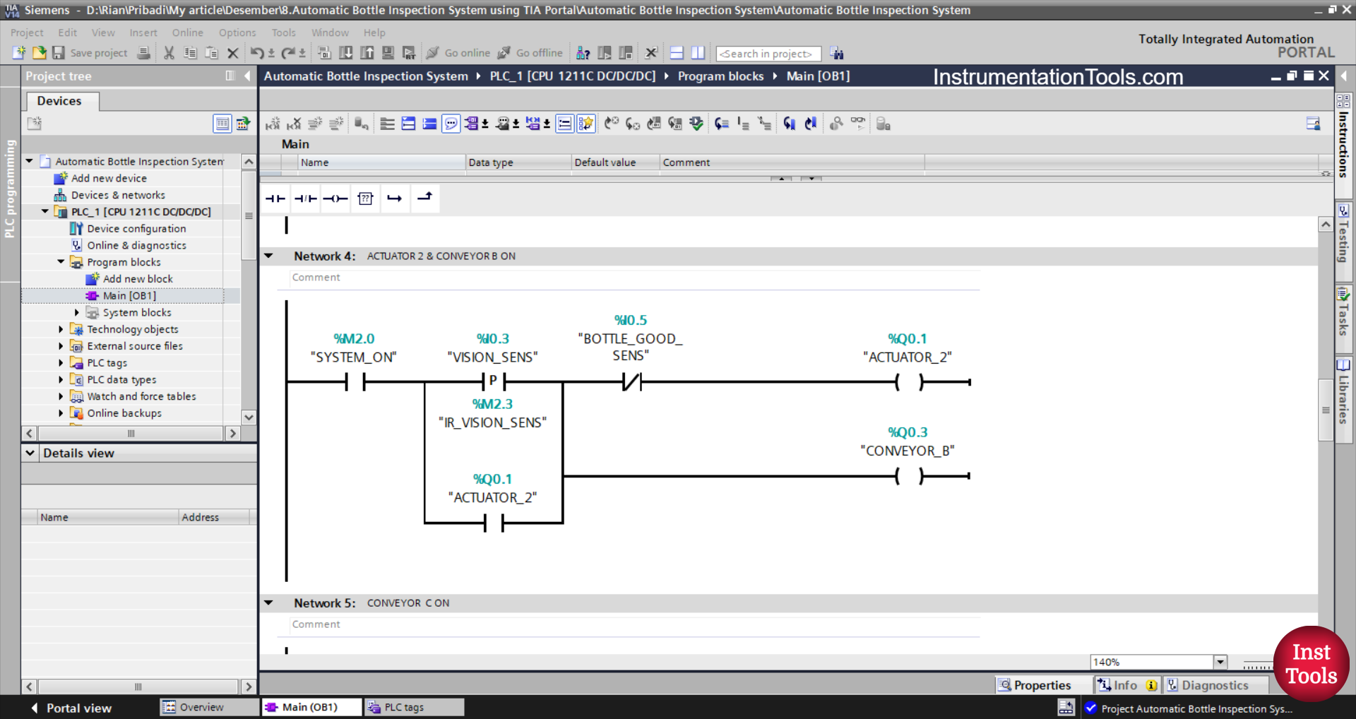
NETWORK 4 (ACTUATOR 2 & CONVEYOR B ON)
The CONVEYOR_B (Q0.1) and ACTUATOR_2 (Q0.1) outputs will be ON when the NO contact of the memory bit SYSTEM_ON (M2.0) and the sensor VISION_SENS (I0.3) are in the HIGH state. Even though the NO contact of the VISION_SENS (I0.3) sensor in the LOW state, the CONVEYOR_B (Q0.1) and ACTUATOR_2 (Q0.1) outputs will remain ON. Because it uses Latching.
When the NC contact of the BOTTLE_GOOD_SENS (I0.5) sensor is in the HIGH state, the CONVEYOR_B (Q0.1) and ACTUATOR_2 (Q0.1) outputs will be OFF.

NETWORK 5 (CONVEYOR C ON)
The CONVEYOR_C (Q0.4) output will be ON if the NO contact of the memory bit SYSTEM_ON (M2.0) and the PROXIMITY_SENS (I0.2) sensor are in the HIGH state. Even though the NO contact of the PROXIMITY_SENS (I0.2) sensor is in the LOW state, the CONVEYOR_C (Q0.4) output will remain ON. Because it uses Latching.
When the NC contact of the BOTTLE_GOOD_SENS (I0.5) sensor and ACTUATOR_2 (Q0.1) are in the HIGH state, the CONVEYOR_C (Q0.4) output will be OFF.
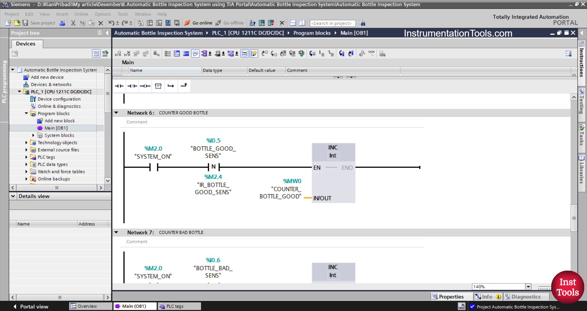
NETWORK 6 (COUNTER GOOD BOTTLE)
In this Network, because it uses the Increment Instruction, the value in the memory word COUNTER_BOTTLE_GOOD (MW0) will increase (+1) when the NO contact of the memory bit SYSTEM_ON (M2.0) and the BOTTLE_GOOD_SENS (I0.5) sensor are in the HIGH state.
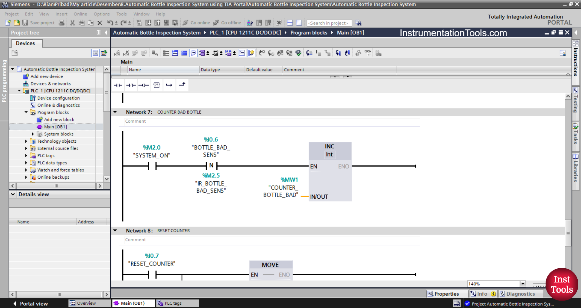
NETWORK 7 (COUNTER BAD BOTTLE)
In this Network, because it uses the Increment Instruction, the value in the memory word COUNTER_BOTTLE_BAD (MW1) will increase (+1) when the NO contact of the memory bit SYSTEM_ON (M2.0) and the BOTTLE_BAD_SENS (I0.6) sensor are in the HIGH state.
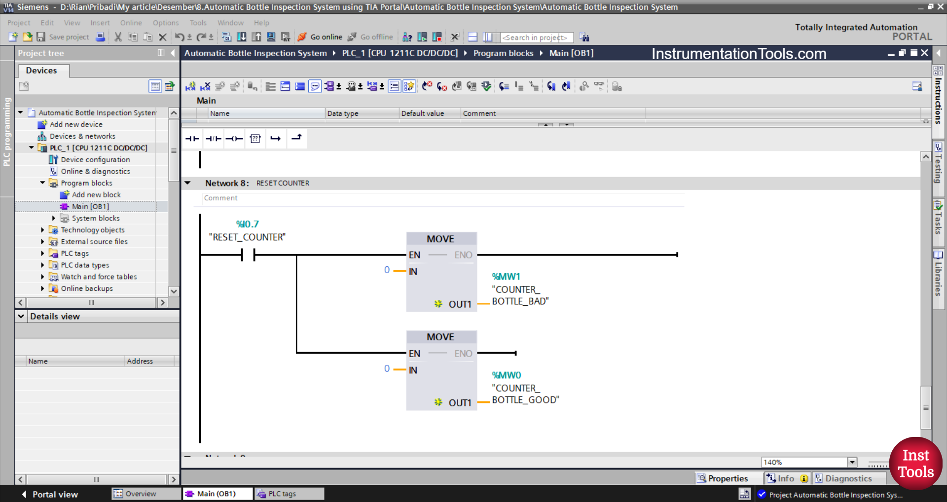
NETWORK 8 (RESET COUNTER)
In this network, because it uses the MOVE instruction, the values in the memory words COUNTER_BOTTLE_GOOD (MW0) and COUNTER_BOTTLE_BAD (MW1) will be reset to zero “0” when the RESET_COUNTER (I0.7) button is pressed. The MOVE instruction moves the zero value “0” to the memory words COUNTER_BOTTLE_GOOD (MW0) and COUNTER_BOTTLE_BAD (MW1).
Read Next:
- Flood Warning System using PLC Programming
- Multi-Tank Liquid Level Control System with Fill Priority
- Siemens PLC Traffic Signal Control with Push Buttons
- TIA Portal Elevator System with Safety Features Program
- PLC Project: Automatic Parking with Vehicle Counter