This article discusses a bottle weight verification system based on Siemens PLC logic. The system is designed to enhance production efficiency by ensuring each bottle is filled to the predetermined capacity through a weighing function. Bottles that are overfilled or Underfilled will be detected and automatically separated. The PLC system includes a feature to count the number of bottles filled with the correct weight.
Program Objective
- Initialization
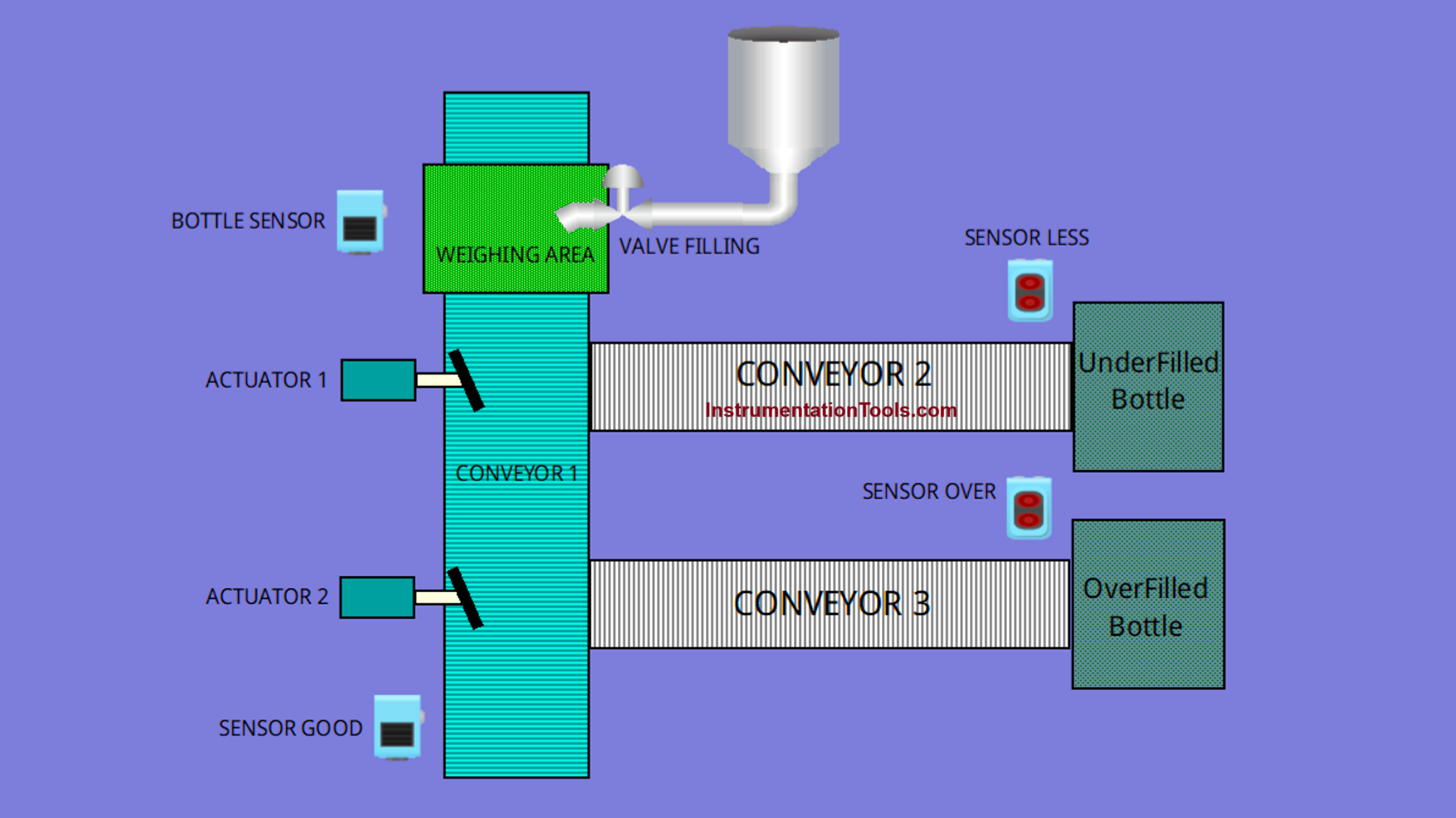
- The main conveyor starts moving, while the system monitors the presence of bottles under the filling valve using sensors.
- Filling Process
- When the Sensor Bottle detects that a bottle is in the correct position, the filling valve will open for 6 seconds.
- After the filling time is completed, the valve will automatically close.
- Next, the system will perform a weighing process to ensure the bottle is filled according to the specified capacity.
- Error Detection
- If the bottle’s content is below the minimum capacity (40 ml), it will be classified as underfilled (less weight) and removed from the main conveyor line.
- If the bottle’s content exceeds the maximum capacity (65 ml), it will be classified as overfilled (Overweight) and also removed from the main conveyor line.
- Separation of Bottles with Incorrect Weight
- Bottles with incorrect weight will be directed to another conveyor line using an actuator.
- Bottles with the correct weight will remain on the main conveyor line and proceed to the next process.
- The system will only count bottles that meet the weight standard.
- Indicator Lights
- The system is equipped with two indicator lights that will illuminate when underfilled or overfilled bottles are detected.
IO Mapping in Siemens PLC Logic
| S.No. | Comment | Input (I) | Output (Q) | Memory Bit | Memory Word | Timer |
|---|---|---|---|---|---|---|
| 1 | PB_START | I0.0 | ||||
| 2 | PB_STOP | I0.1 | ||||
| 3 | SENS_BOTTLE | I0.2 | ||||
| 4 | SENS_OUT_OVER | I0.3 | ||||
| 5 | SENS_OUT_LESS | I0.4 | ||||
| 6 | SENS_OUT_GOOD | I0.5 | ||||
| 7 | RESET_COUNTER | I0.6 | ||||
| 8 | CONVEYOR_1 | Q0.0 | ||||
| 9 | VALVE_FILLING | Q0.1 | ||||
| 10 | ACTUATOR_1 | Q0.2 | ||||
| 11 | ACTUATOR_2 | Q0.3 | ||||
| 12 | LAMP_BOTTLE_OVERWEIGHT | Q0.4 | ||||
| 13 | LAMP_BOTTLE_LESSWEIGHT | Q0.5 | ||||
| 14 | CONVEYOR_2 | Q0.6 | ||||
| 15 | CONVEYOR_3 | Q0.7 | ||||
| 16 | PV_LIQUID | MW0 | ||||
| 17 | COUNTER_GOOD_BOTTLE | MW1 | ||||
| 18 | SYSTEM_ON | M2.0 | ||||
| 19 | IR_SENS_BOTTLE | M2.1 | ||||
| 20 | IR_SENS_OUT_GOOD | M2.2 | ||||
| 21 | TIMER_DELAY | DB1 |
Bottle Weight Verification System
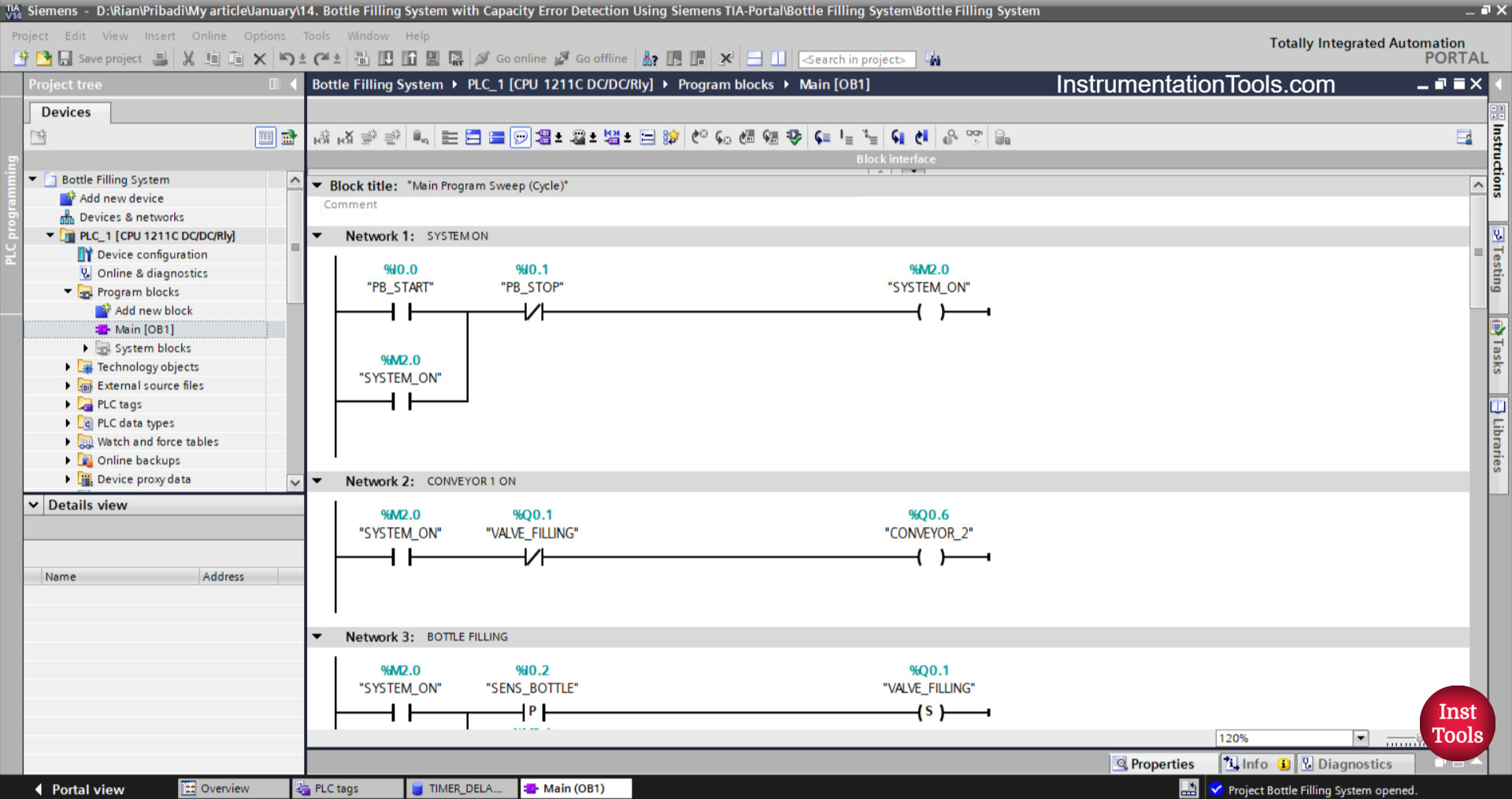
NETWORK 1 (SYSTEM ON)
In this network, when the PB_START (I0.0) button is pressed, the memory bit SYSTEM_ON (M2.0) will be in the HIGH state. Because it uses Latching, even though the PB_START (I0.0) button has been released, the memory bit SYSTEM_ON (M2.0) will remain in the HIGH state.
The memory bit SYSTEM_ON (M2.0) will be in the LOW state if the PB_STOP (I0.1) button is pressed.
NETWORK 2 (CONVEYOR 1 ON)
In this Network, the output CONVEYOR_1(Q0.0) will be ON when the NO contact of the memory bit SYSTEM_ON (M2.0) is in the HIGH state. If the NC contact of VALVE_FILLING (Q0.1) is in the HIGH state, then the output CONVEYOR_1 (Q0.0) will be OFF.
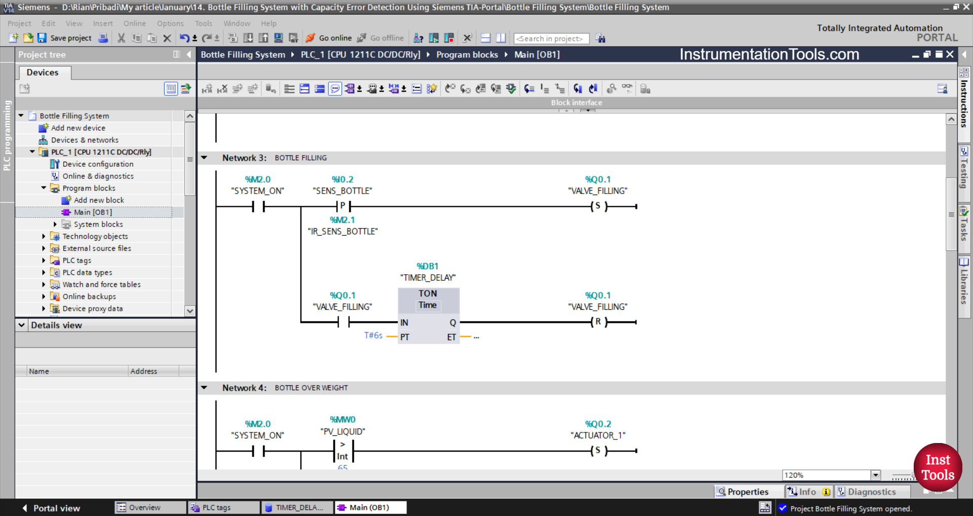
NETWORK 3 (BOTTLE FILLING)
In this Network, the VALVE_FILLING (Q0.1) output will be OPEN if the NO contact of the memory bit SYSTEM_ON (M2.0) and the SENS_BOTTLE (I0.2) sensor are in the HIGH state.
Next, the TIMER_DELAY (DB1) timer will start counting up to 6 seconds, and when finished counting, the VALVE_FILLING (Q0.1) output will become CLOSE.
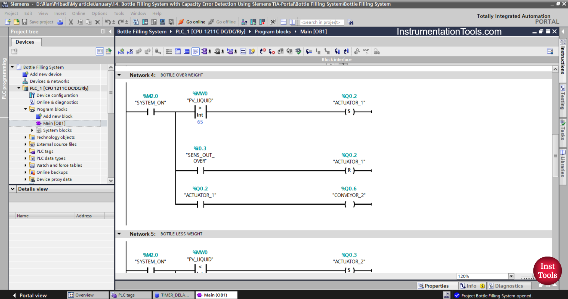
NETWORK 4 (BOTTLE OVER WEIGHT)
In this network, when the NO contact of the memory bit SYSTEM_ON (M2.0) is in the HIGH state and the memory word PV_LIQUID (MW0) has a value Greater Than “65”, then the output ACTUATOR_1 (Q0.2) will be ON.
If the NO contact of the SENS_OUT_OVER (I0.3) sensor is in the HIGH state, then the ACTUATOR_1 (Q0.2) output will be OFF.
When the NO contact of ACTUATOR_1 (Q0.2) is in the HIGH state, the output of CONVEYOR_2 (Q0.6) will be ON.
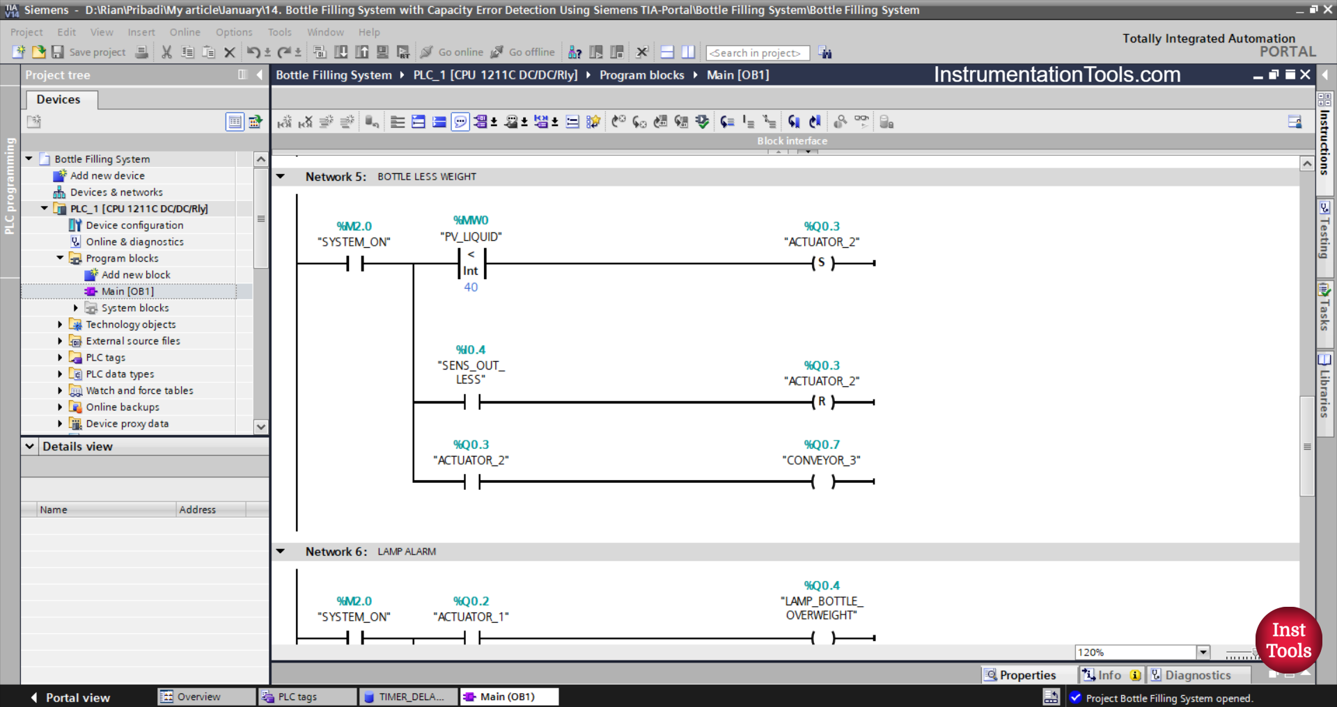
NETWORK 5 (BOTTLE LESS WEIGHT)
In this network, when the NO contact of the memory bit SYSTEM_ON (M2.0) is in the HIGH state and the memory word PV_LIQUID (MW0) is Less Than “40”, then the ACTUATOR_2 (Q0.3) output will be ON.
If the NO contact of the SENS_OUT_LESS (I0.4) sensor is in the HIGH state, then the ACTUATOR_2 (Q0.3) output will be OFF.
When the NO contact of ACTUATOR_2 (Q0.3) is in the HIGH state, the output CONVEYOR_3 (Q0.7) will be ON.
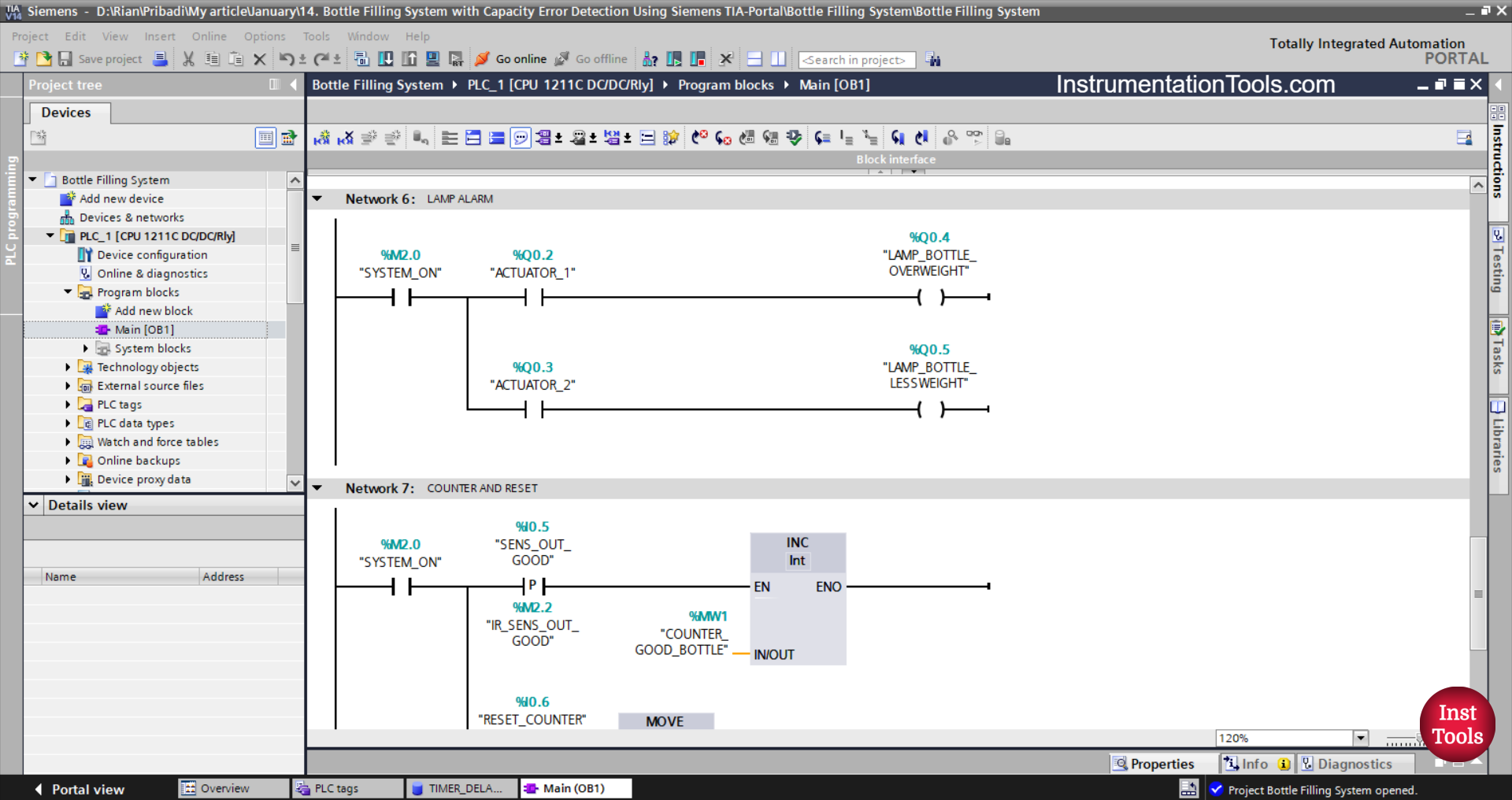
NETWORK 6 (LAMP ALARM)
In this Rung, if the NO contacts of the memory bits SYSTEM_ON (M2.0) and ACTUATOR_1 (Q0.2) are in the HIGH state, then the output LAMP_BOTTLE_OVERWEIGHT (Q0.4) will be ON
When the NO contacts of the memory bits SYSTEM_ON (M2.0) and ACTUATOR_2 (Q0.3) are in the HIGH state, the output LAMP_BOTTLE_LESSWEIGHT (Q0.5) will be ON.
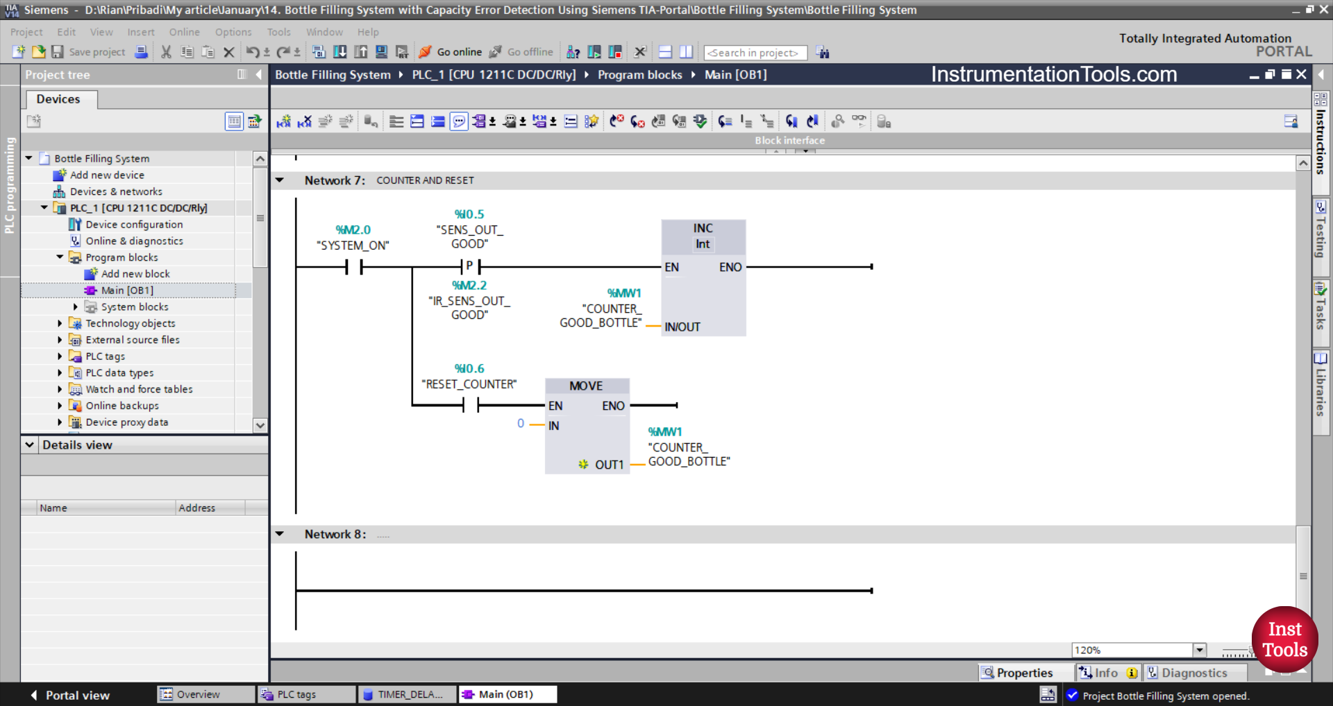
NETWORK 7 (COUNTER AND RESET)
In this network, if the NO contact of the memory bit SYSTEM_ON (M2.0) and the SENS_OUT_GOOD (I0.5) sensor are in the HIGH state, then the value in the memory word COUNTER_GOOD_BOTTLE (MW1) will increase by (+1).
And, when the NO contact of the memory bit SYSTEM_ON (M2.0) in the HIGH state and the RESET_COUNTER (I0.6) button is pressed, the value in the memory word COUNTER_GOOD_BOTTLE (MW1) will be reset to zero “0”.
Read Next:
- Gas Monitoring Logic with Siemens PLC
- Top Common Causes for PLC System Failure
- Multi-Level Parking Control Program in TIA Portal
- Paint Mixing System Control Program using TIA-Portal
- How to Download WPLSoft? Delta PLC Software