Loop control plays a critical role in industrial automation and instrumentation engineering. Essentially, it ensures that all signals in a control loop are properly connected and functioning according to the desired specifications. If you are commissioning an automation project and you are not thorough with your loop testing, then your system might fail at any time. In that, two types of loop control testing in automation and instrumentation are hot loop testing and cold loop testing. Both are opposite in operation and functionality. In this post, we will see the difference between hot and cold loop checking in industrial automation.
What is a Loop Control?
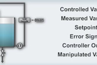
First of all, let us understand what a loop control is. In instrumentation, a loop control is defined as a process that reads an input variable, compares it with the set point, and takes the necessary action to keep the input variable near that set point. In simple terms, we can also describe it as a PID function, which continuously monitors a process variable and compares it with a fixed value, and takes the required control action to keep that process variable near that fixed value. This function is performed in a controller like a PLC.
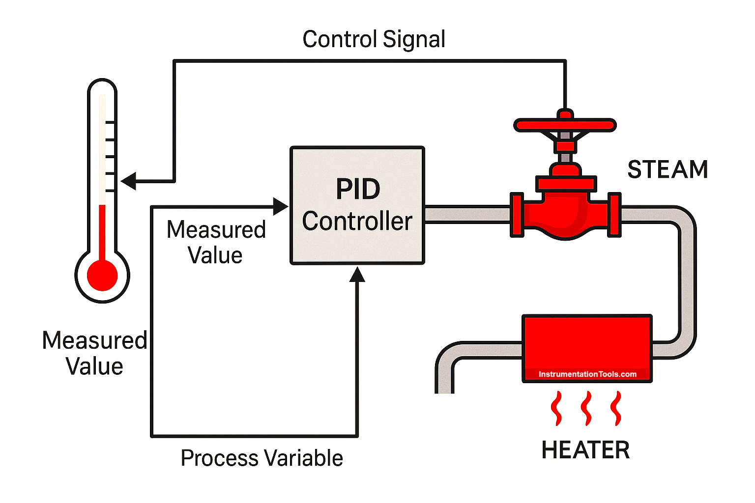
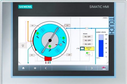
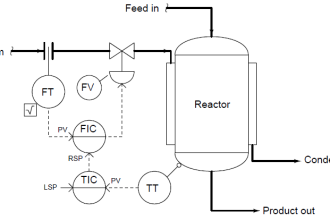
For example, consider a steam valve that is used to control the flow of steam through it. A temperature sensor is mounted on its discharge line, and its feedback is given to the PLC in a closed-loop manner. The operator has set a value of 85 degrees of steam that needs to be maintained in the pipeline. If the temperature rises above the set point, the valve will start to close itself to allow less steam to pass. If the temperature goes below the set point, the valve will start to open itself to allow more steam to pass. The valve is being controlled by the PLC as it is reading the temperature sensor value, and throttling or actuating the valve accordingly to maintain the steam temperature in the system. This is called a loop control, as a temperature loop is continuously monitored by the PLC and controlled to maintain the required value. Refer to the image below for more details.
What is Cold Loop Testing?
Now that we are clear about what loop control is, let us begin our topic. First, let us start with cold loop testing. As the name implies, cold loop testing is a process that is performed in a power-off condition. The main purpose of the cold loop is to check all the wiring connections before powering on the process. That is done by checking the continuity of the wiring ends. All the sensors, actuators, and controllers are cold loop tested by checking whether the wiring is connected and terminated to the point correctly.
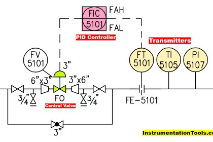
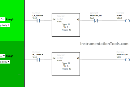
For example, consider a PLC having an analog input of 4-20 mA (for sensor) and an analog output of 4 to 20 mA (for actuator). The field instrument (sensor or actuator here) will have its wire connected to the terminal block of the PLC panel. From there, the wire will go to the PLC input or output. Simply cold loop testing here means the first set of wire from the field instrument to the terminal block has continuity between both of them, and the second set of wire from the terminal block to the PLC has continuity between both of them. Due to this, it will be ensured that the field instrument has been connected to the PLC with full continuity. Refer to the image below for more details.

What is Hot Loop Testing?
As the name implies, hot loop testing is a process that is performed in a power-on condition. The main purpose of the hot loop is to check all the loop functionalities in live conditions and verify that the loop is being controlled and monitored accurately, after the wiring has been checked in cold loop testing. All the sensors, actuators, and controllers are hot loop tested by checking whether the control element is controlling the monitor element according to its change.
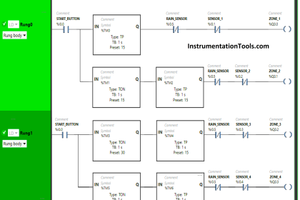
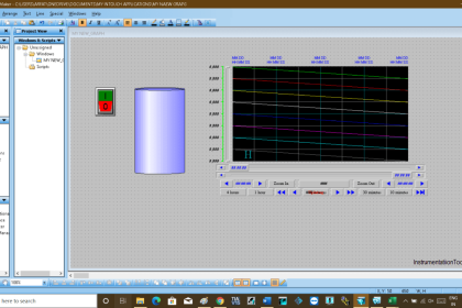
Continuing our example discussed before, the sensor value is simulated by increasing or decreasing its value. Accordingly, the control valve action is checked to see whether it is increasing or decreasing. If it is working in proportion to the changes, then that means your hot loop has been tested. If the variation is large, then the temperature cannot be able to be controlled, and you need to do proper tuning of the PID parameters or check the output of the sensor or control valve.
Cold Loop Testing vs Hot Loop Testing
| Cold Loop Testing | Hot Loop Testing |
|---|---|
| Cold loop testing checks the wiring and continuity without energizing the system. | Hot loop testing verifies signal flow with the system energized and powered on. |
| Cold loop testing is performed with the system de-energized (no power to field devices). | Hot loop testing is performed with the system energized (power applied to field devices). |
| Cold loop testing is used to verify physical wiring, I/O card mapping, and signal continuity. | Hot loop testing confirms proper signal transmission and response in live systems. |
| Cold loop testing uses manual simulation or jumpers at the field terminal. | Hot loop testing uses actual signals from powered field instruments or transmitters. |
| Cold loop testing is done without activating the PLC or DCS controller. | Hot loop testing requires the PLC or DCS to be active and running. |
| Cold loop testing does not require field devices to be functional or powered. | Hot loop testing requires all field devices to be installed and operational. |
| Cold loop testing verifies only wiring accuracy and continuity. | Hot loop testing verifies functional accuracy and real signal integrity. |
| Cold loop testing confirms only partial loop integrity (wiring and terminations). | Hot loop testing confirms full loop integrity from instrument to controller. |
| Cold loop testing uses resistance or continuity checks via a multimeter or simulator. | Cold loop testing is usually done during the pre-commissioning or cable verification phase. |
| Cold loop testing is safer, as it involves no live voltage or current. | Hot loop testing is riskier and requires safety precautions due to live systems. |
| Cold loop testing is usually done during pre-commissioning or cable verification phase. | Hot loop testing involves live signal monitoring using tools like a HART communicator. |
| Cold loop testing is used to identify wiring mistakes, open circuits, or wrong terminals. | Hot loop testing is used to verify loop functionality, signal levels, and response. |
| Cold loop testing does not cover the full loop path, only part of it. | Hot loop testing covers the entire loop path and functionality. |
| Cold loop testing generally requires only basic documentation of continuity checks. | Hot loop testing requires detailed records of instrument response and signal values. |
| Hot loop testing is performed during final commissioning or the startup phase. | Cold loop testing includes examples like verifying 4–20mA loop continuity to the PLC input. |
- Cold testing is performed before commissioning or when the power is not present in the system. Hot loop testing is performed during commissioning or when the power is live in the system.
- The purpose of cold loop testing is to check continuity and the I/O testing, whereas the purpose of hot loop testing is to check the functionality of the system in live conditions, depicting whether the control loop is performing as per desired specifications or not.
- Cold testing has fewer safety considerations, whereas hot loop testing has higher safety considerations and needs to be followed properly as per the rules and regulations.
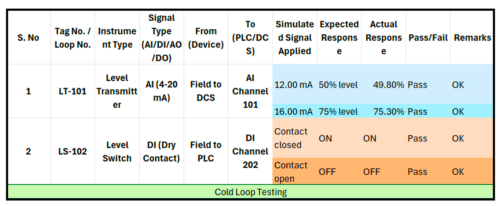
Refer to the image below for a clear comparison between cold loop testing and hot loop testing. It can be seen that the cold loop was intended to just check the wiring and whether the desired value is coming in that I/O or not; whereas the hot loop was intended to check the PID or control loop algorithm by seeing whether the sensor is properly controlled by the valve or not.

In this way, we saw the difference between hot loop testing and cold loop testing in industrial automation.
Read Next:
- Process Control & Safety Systems Logics
- Standard Colors in PLC Automation Systems
- What is NAMUR OPEN ARCHITECTURE?
- System Architecture in an Automation Plant
- Design Logic Diagrams for Process Control


nice article