Inst ToolsInst ToolsInst Tools
  • Courses
  • Automation
    • PLC
    • Control System
    • Safety System
    • Communication
    • Fire & Gas System
  • Instrumentation
    • Design
    • Pressure
    • Temperature
    • Flow
    • Level
    • Vibration
    • Analyzer
    • Control Valve
    • Switch
    • Calibration
    • Erection & Commissioning
  • Interview
    • Instrumentation
    • Electrical
    • Electronics
    • Practical
  • Q&A
    • Instrumentation
    • Control System
    • Electrical
    • Electronics
    • Analog Electronics
    • Digital Electronics
    • Power Electronics
    • Microprocessor
  • Request
Search
  • Books
  • Software
  • Projects
  • Process
  • Tools
  • Basics
  • Formula
  • Power Plant
  • Root Cause Analysis
  • Electrical Basics
  • Animation
  • Standards
  • 4-20 mA Course
  • Siemens PLC Course
Reading: What is a Fieldbus?
Share
Notification Show More
Font ResizerAa
Inst ToolsInst Tools
Font ResizerAa
  • Courses
  • Design
  • PLC
  • Interview
  • Control System
Search
  • Courses
  • Automation
    • PLC
    • Control System
    • Safety System
    • Communication
    • Fire & Gas System
  • Instrumentation
    • Design
    • Pressure
    • Temperature
    • Flow
    • Level
    • Vibration
    • Analyzer
    • Control Valve
    • Switch
    • Calibration
    • Erection & Commissioning
  • Interview
    • Instrumentation
    • Electrical
    • Electronics
    • Practical
  • Q&A
    • Instrumentation
    • Control System
    • Electrical
    • Electronics
    • Analog Electronics
    • Digital Electronics
    • Power Electronics
    • Microprocessor
  • Request
Follow US
All rights reserved. Reproduction in whole or in part without written permission is prohibited.
Inst Tools > Blog > Communication > What is a Fieldbus?

What is a Fieldbus?

Last updated: March 19, 2020 2:06 pm
Editorial Staff
Communication
2 Comments
Share
4 Min Read
SHARE

Fieldbus is a digital two-way multidrop communication link between intelligent field devices. It is a local area network dedicated to industrial automation. It replaces centralized control networks with distributed control networks and links the isolated field devices such as smart sensors/ transducers/actuators/controllers.

Contents
FieldbusHART Versus Fieldbus DevicesHistory

Fieldbus

Foundation Fieldbus H1 and PROFIBUS-PA are the two fieldbus technologies used in process control. In this two-way communication, it is possible to read data from the smart sensor and also write data into it. The multidrop communication facility in fieldbus results in enormous cable savings and resultant cost reduction.

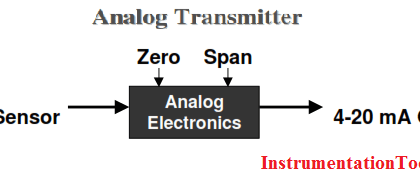
A fieldbus device must have a fieldbus interface unit for proper communication to take place, and is shown in Figure.

A comparison between a 4–20 mA system and a fieldbus system is shown in Table.

fieldbus-system-and-4-20ma-system

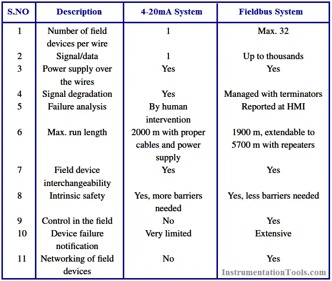
A conventional 4–20 mA current transmission system has two wires each for each of the individual field devices employed.

HART Versus Fieldbus Devices

Compared with this, a fieldbus system has two wires running for many devices that belong to the same segment. A segment may consist of 32 devices.

fieldbus-vs-4-20ma

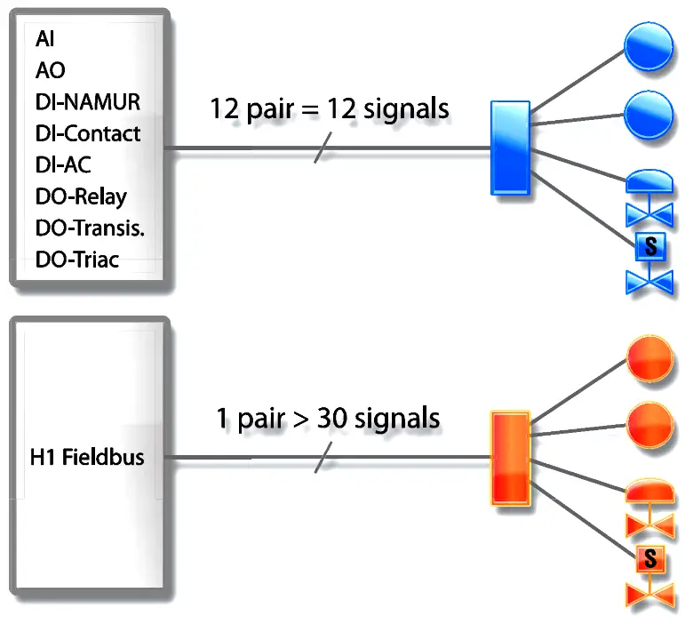
The above Figure shows a conventional point-to-point communication system and its fieldbus counterpart. There are as many wire pairs as the number of field devices for a point-to-point communication system, while it can be only a single wire pair for a fieldbus system.

History

With digital communication making its way into process automation systems several decades back, different vendors started developing their own protocols—independent of each other. In the initial stages of fieldbus introduction, design engineers were confronted with several problems.

First, a particular vendor could not provide all the parts/components needed for a plant and that a particular manufacturer cannot make all the devices better than others. This led to either choosing the less-than-the-best devices from a single manufacturer or else settling for choosing the best devices from different manufacturers.

The latter option would give rise to an integrability problem and lead to isolated islands of automation and consequent inter operability difficulty with devices from different manufacturers.

transmitter-fieldbus

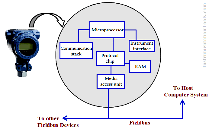
Fig : Fieldbus interface unit in a fieldbus transmitter

Initially when fieldbus was introduced, it suffered from numerous problems such as proprietary protocols, slow transmission speed, and different data formats. Improvements in field signal transmission technology resulted in increasing levels of decentralization.

In 1985, industry experts in the field sat together to work out a vendor independent fieldbus standard—i.e., it would be interoperable. The bus standard would provide bus power, intrinsic safety, and the ability to communicate long distances over existing wires—the basic requirements for a process plant automation system.

Partly due to the complexities of instrumentation automation systems and mostly due to the reluctance on the part of the manufacturers, a single standard protocol architecture is yet to be established. Foundation Fieldbus and PROFIBUS are now the two most dominant fieldbus technologies that are ruling the process automation field. Devices embracing these two technologies cannot communicate with each other because of protocol mismatch and thus seamless interoperability is yet to be achieved.

There are many types of fieldbuses in use today; the particular type to be used depends on the type of industry—discrete or manufacturing automation. Different types of fieldbuses include: Foundation Fieldbus, PROFIBUS, DeviceNet, ControlNet, InterBus, HART, AS-i, MODBUS, CAN Bus, Ethernet, LonWorks, and WorldFIP.

Also See : 4-20mA Versus Fieldbus Animation

Don't Miss Our Updates
Be the first to get exclusive content straight to your email.
We promise not to spam you. You can unsubscribe at any time.
Invalid email address
You've successfully subscribed !

Continue Reading

Difference Between Serial and Parallel Communication
CANOpen Network Topology
Difference Between Modbus TCP IP and Profinet
OPC Solves Automation’s Data Connectivity
Difference between Router, Switch, and Hub
Different Fieldbus Network Topologies
Share This Article
Facebook Whatsapp Whatsapp LinkedIn Copy Link
Share
2 Comments
  • Hemal Vadgama says:
    September 15, 2016 at 7:43 am

    Very Easy good for learn about instrumentation.

    Reply
  • V J says:
    November 23, 2016 at 4:30 am

    Very useful and good information, easy to understand too. Since I am in teaching profession, It will be very useful to me

    Reply

Leave a Reply Cancel reply

Your email address will not be published. Required fields are marked *

Stay Connected

128.3kFollowersLike
69.1kFollowersFollow
210kSubscribersSubscribe
38kFollowersFollow

Categories

Explore More

7 OSI Layers of Communication
Foundation Fieldbus Signal Conversion Formula
Profinet Communication – Specifications, Example, Advantages
Types of Wireless Technologies in Industrial Automation
Difference between Fieldbus and Profibus
DNP3 Communication Protocol Overview
Difference Between RS232 and RS485
What is Rapid Spanning Tree Protocol? – RSTP Network

Keep Learning

Profibus network

How Profibus Communication Works

What is Profibus

All About Fieldbus Protocols

Tree (chicken foot) topology

Fieldbus Device Capability

Fieldbus Interview Questions

Interview Questions on Fieldbus Communication

Fieldbus Flow Transmitter Calibration

Foundation Fieldbus Transmitter Calibration

RAID stands for Redundant Array of Independent Disks

What is Raid Parity? – Types, Advantages, Disadvantages

Fieldbus Analog Input Function Block

fieldbus cables layout

H1 FF Data Link layer

Learn More

Spring Loaded Variable Area Flowmeter Working Principle

Spring Loaded Variable Area Flow Meter Working Principle

Variable Area Flow Meters

All About Variable Area Flow Meters

Difference between Force and Power

Difference between Force and Power

Well Manometer Principle

Well Manometer Principle

MOS Gas Sensor Principle

MOS Type Gas Sensor Principle

Fuse in a Electrical Circuit

Advantages & Disadvantages of Fuse in a Electrical Circuit

Oxygen Measurement using Tunable Diode Laser System

Tunable Diode Laser Analyzer Working Principle

Modbus Vs DNP3

Difference between Modbus and DNP3 Communication Protocols

Menu

  • About
  • Privacy Policy
  • Copyright

Quick Links

  • Learn PLC
  • Helping Hand
  • Part Time Job

YouTube Subscribe

Follow US
All rights reserved. Reproduction in whole or in part without written permission is prohibited.
Welcome Back!

Sign in to your account

Username or Email Address
Password

Lost your password?