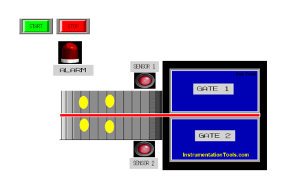
This article will discuss an automatic garage door control system using XG5000 PLC logic. The PLC system aims to provide convenience and safety in opening and closing garage doors with two modes of operation: automatic mode and manual mode. The system allows the garage door to open and close when a car is entering or exiting.
Program Objective

How does the System work?
Mode Selection:
The user selects the garage door operation mode using the mode switch (Auto/Manual).
Automatic Mode:
- In automatic mode, the system operates based on the Limit Switch and Object Sensor.
- When a car approaches and is detected by the sensor, the system will automatically open the garage door.
- After the car enters or Exits, and the sensor no longer detects the car, the system will automatically close the garage door.
Manual Mode:
- In manual mode, the user can open or close the garage door using the available Open/Close button.
- The system will activate the door motor according to the command from the Open/Close button.
Limit Switch:
- The Limit Switch provides feedback to the system regarding the position of the garage door (whether it is Open or Closed).
- The system will use this feedback signal to control the door’s movement and ensure the door stops at the correct position (fully open or fully closed).
Garage Door Opening and Closing Logic
IO Mapping
| S.No. | Comment | Input (I) | Output (Q) | Memory Bit |
|---|---|---|---|---|
| 1 | PB_START | P0000 | ||
| 2 | PB_STOP | P0001 | ||
| 3 | AUTO_MANUAL | P0002 | ||
| 4 | PB_OPEN | P0003 | ||
| 5 | PB_CLOSE | P0004 | ||
| 6 | SENS_1 | P0005 | ||
| 7 | SENS_2 | P0006 | ||
| 8 | LS_LOW | P0007 | ||
| 9 | LS_HIGH | P0008 | ||
| 10 | DOOR_OPEN | P0040 | ||
| 11 | DOOR_CLOSE | P0041 | ||
| 12 | IR1_DOOR_OPEN | M0000 | ||
| 13 | IR2_DOOR_OPEN | M0001 | ||
| 14 | IR1_DOOR_CLOSE | M0002 | ||
| 15 | IR2_DOOR_CLOSE | M0003 | ||
| 16 | SYSTEM_ON | M0004 | ||
| 17 | IL_CAR_IN | M0005 | ||
| 18 | IL_CAR_OUT | M0006 |
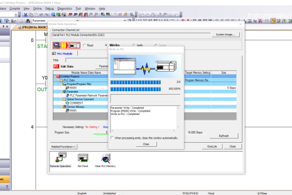
XG5000 PLC Programming

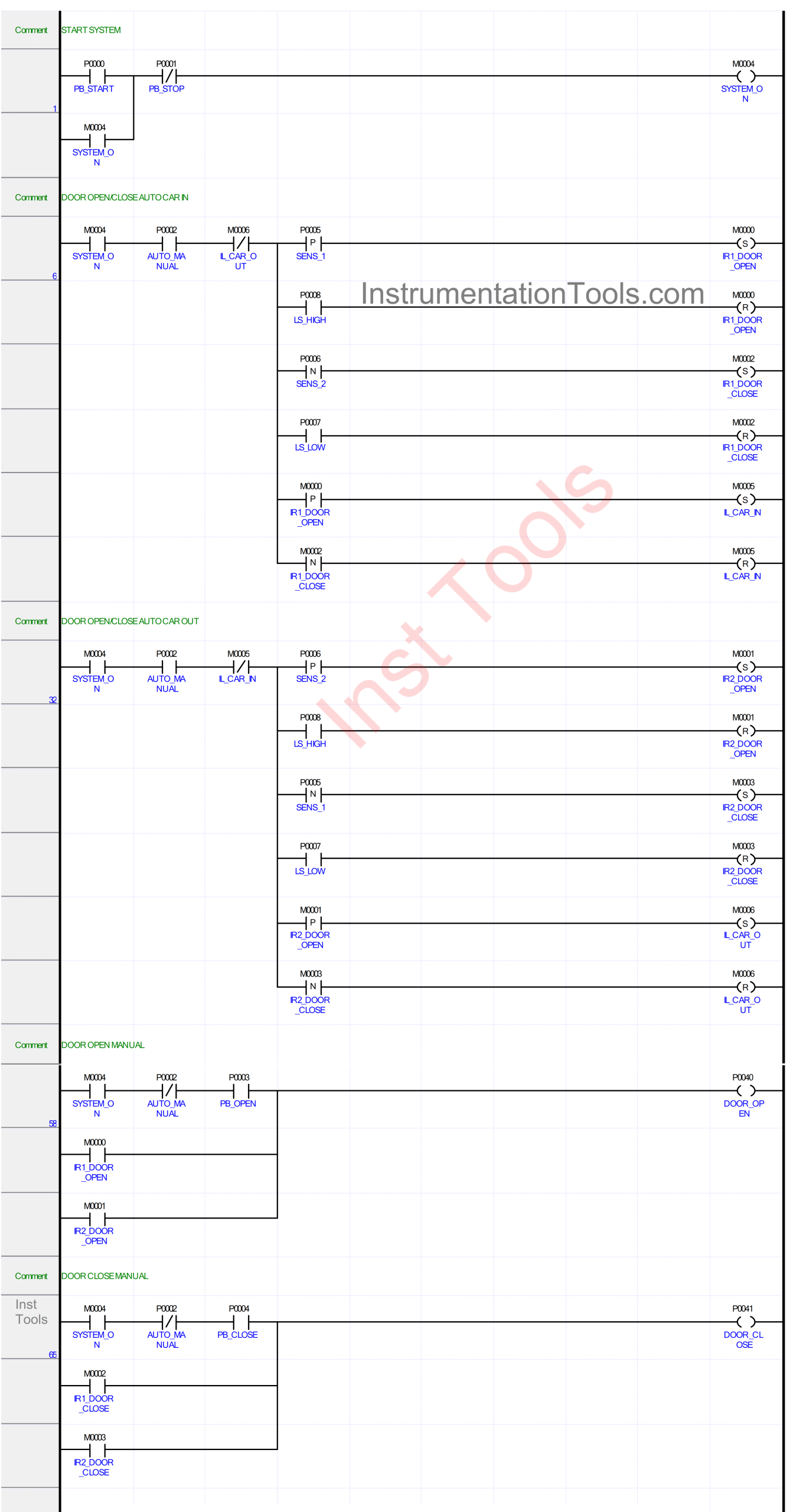
RUNG 1 (START SYSTEM)
In this rung, if the PB_START (P0000) button is Pressed, the memory bit SYSTEM_ON(M0004) will be in the HIGH state. Because it uses Latching, the memory bit SYSTEM_ON (M0004) will remain in the HIGH state even though the PB_START (P0000) button has been Released.
The memory bit SYSTEM_ON (M0004) will return to the LOW state if the PB_STOP (P0001) button has been Pressed.

RUNG 6 (DOOR OPEN/CLOSE AUTO CAR IN)
In this Rung, the memory bit IR1_DOOR_OPEN (M0000) will be in the HIGH state if the NO contact of the memory bit SYSTEM_ON (M0004), selector switch AUTO_MANUAL (P0002), and sensor SENS_1 (P0005) are in the HIGH state. The memory bit IR1_DOOR_OPEN (M0000) will return to the LOW state if the NO contact of the limit switch LS_HIGH (P0008) is in the HIGH state.
The memory bit IR1_DOOR_CLOSE (M0002) will be in the HIGH state if the NO contact of the memory bit SYSTEM_ON (M0004), selector switch AUTO_MANUAL (P0002), and sensor SENS_2 (P0006) are in the HIGH state. The memory bit IR1_DOOR_CLOSE (M0002) will return to the LOW state if the NO contact of the limit switch LS_LOW (P0007) is in the HIGH state.
And, the memory bit IL_CAR_IN (M0005) will be in the HIGH state if the NO contacts of the memory bits SYSTEM_ON (M0004), IR1_DOOR_OPEN (M0000), and selector switch AUTO_MANUAL (P0002) are in the HIGH state. The memory bit IL_CAR_IN (M0005) will return to the LOW state if the NO contact of the memory bit IR1_DOOR_CLOSE (M0002) is in the HIGH state.
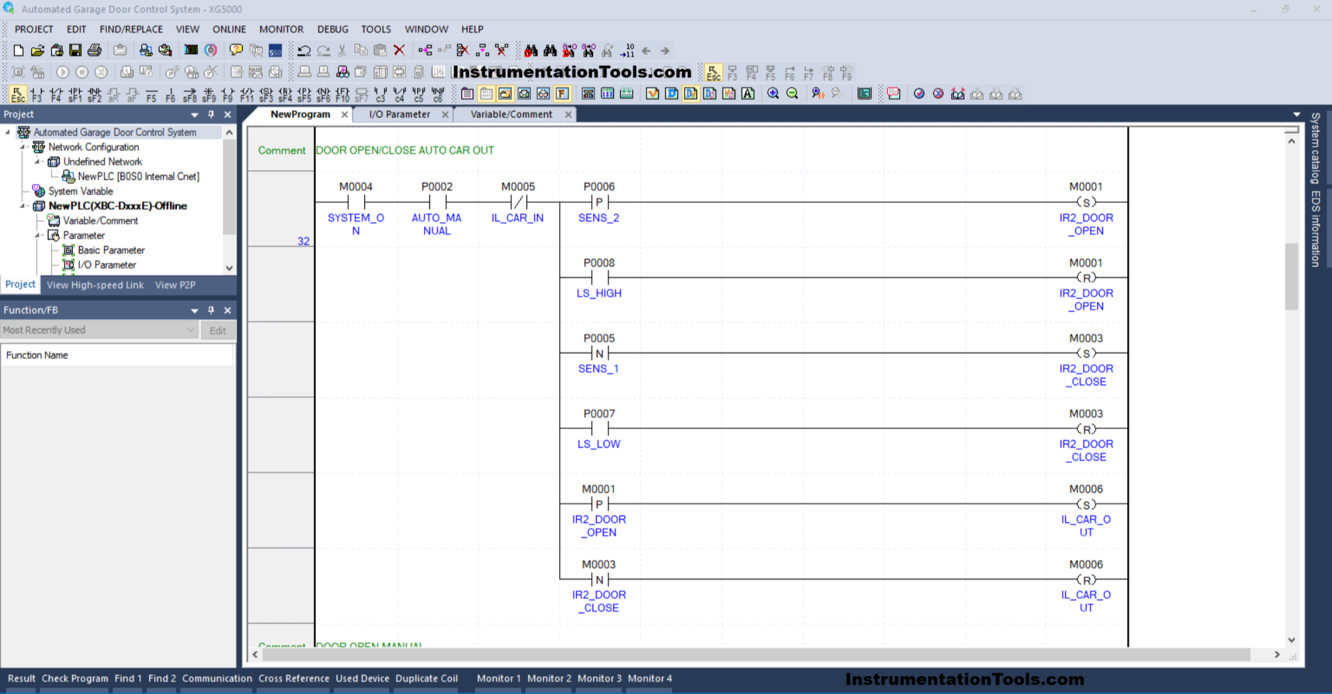
RUNG 32 (DOOR OPEN/CLOSE AUTO CAR OUT)
In this Rung, the memory bit IR2_DOOR_OPEN (M0001) will be in the HIGH state if the NO contact of the memory bit SYSTEM_ON (M0004), selector switch AUTO_MANUAL (P0002), and sensor SENS_2 (P0006) are in the HIGH state. The memory bit IR2_DOOR_OPEN (M0001) will return to the LOW state if the NO contact of the limit switch LS_HIGH (P0008) is in the HIGH state.
The memory bit IR2_DOOR_CLOSE (M0003) will be in the HIGH state if the NO contact of the memory bit SYSTEM_ON (M0004), selector switch AUTO_MANUAL (P0002), and sensor SENS_1 (P0005) are in the HIGH state. The memory bit IR2_DOOR_CLOSE (M0003) will return to the LOW state if the NO contact of the limit switch LS_LOW (P0007) is in the HIGH state.
And, the memory bit IL_CAR_OUT (M0006) will be in the HIGH state if the NO contacts of the memory bits SYSTEM_ON (M0004), IR2_DOOR_OPEN (M0001), and selector switch AUTO_MANUAL (P0002) are in the HIGH state. The memory bit IL_CAR_OUT (M0006) will return to the LOW state if the NO contact of the memory bit IR2_DOOR_CLOSE (M0003) is in the HIGH state.

RUNG 58 (DOOR OPEN MANUAL)
In this Rung, the DOOR_OPEN (P0040) output will be ON if the NO contact of the memory bit SYSTEM_ON (M0004), and the PB_OPEN (P0003) button is Pressed.
The DOOR_OPEN (P0040) output will also be ON if the NO contact of the memory bits IR1_DOOR_OPEN (M0000) or IR2_DOOR_OPEN (M0001) is in the HIGH state.
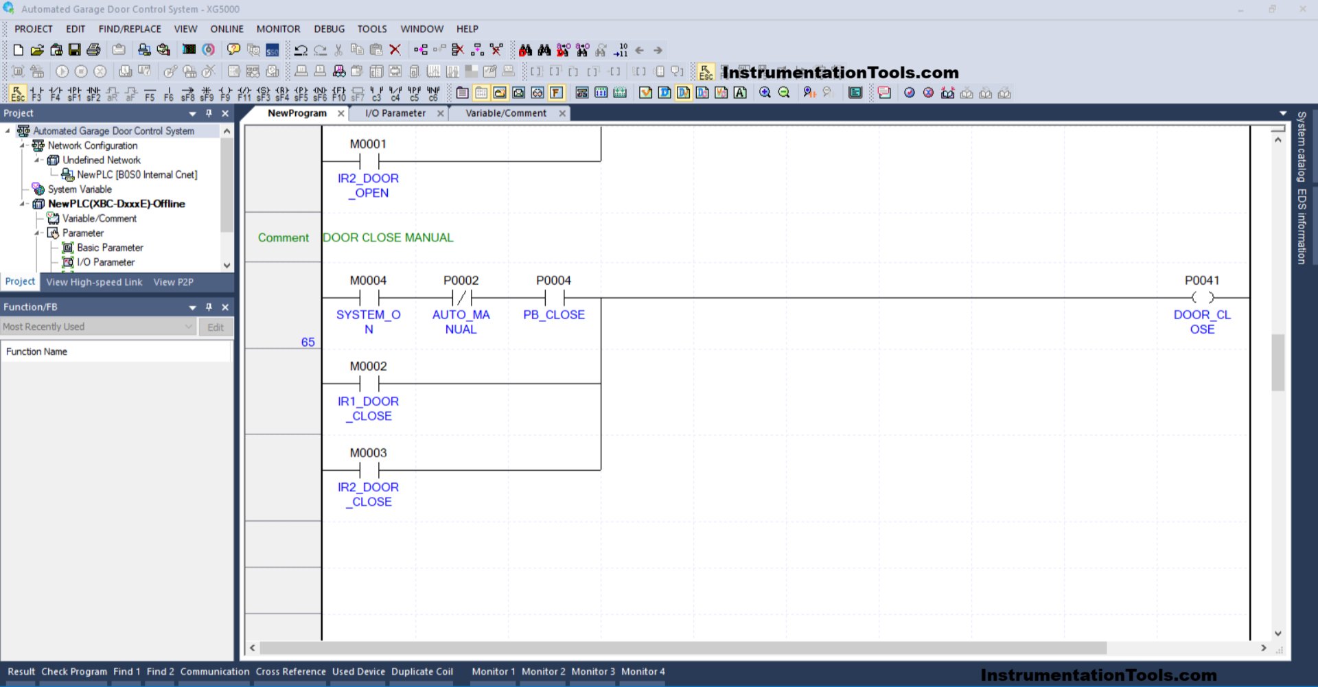
RUNG 65 (DOOR CLOSE MANUAL)
In this Rung, the DOOR_CLOSE(P0041) output will be ON if the NO contact of the memory bit SYSTEM_ON (M0004), and the PB_CLOSE (P0004) button is Pressed.
The DOOR_CLOSE (P0041) output will also be ON if the NO contact of the memory bits IR1_DOOR_CLOSE (M0002) or IR2_DOOR_CLOSE (M0003) is in the HIGH state.
Read Next:
- Vehicle Washing PLC Project: Spray, Brush, Rinse, Dry
- PLC Program to Mix 4 Materials with Time and Weight
- Read Mitsubishi PLC Analog Input and Display in HMI
- Omron PLC Program for 4 Conveyor Interlock System
- Communicate Modbus Poll Software with Mitsubishi PLC