This article discusses the analog voltage output control using the Mitsubishi PLC with the Weintek HMI MT6071IE. The HMI device can be used to change input parameters and data in the PLC word memory. In this system, a digital resolution value (0-4095) is provided through input parameters that have been created on the Weintek MT6071IE HMI interface. Then, this value is converted by the PLC into a 0-10V analog voltage signal.
Required Devices
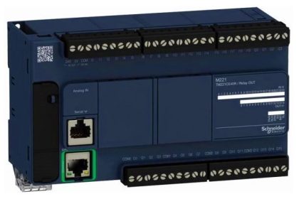
PLC FX3U-14MT Lollette:
This PLC features 8 digital inputs, 6 transistor outputs, 4 analog inputs, and 2 analog outputs. Uses a 24V DC power supply and an RS232 DB9 port (38.4 Kbps). Suitable for education and small projects, less ideal for large-scale industrial applications.
Software EasyBuilder Pro:
The EasyBuilder Pro is used to design HMI interfaces and configure communication parameters for Weintek devices.
HMI MT6071IE:
This HMI is a 7-inch touchscreen with COM1 (RS232), COM2 & COM3 (RS485) ports, and a mini USB type B for design transfer. Compatible with Mitsubishi FX series PLCs and various other PLC types.
Software GX Works2:
This is official Mitsubishi software for programming MELSEC series PLCs (FX3U, FX5U). Used to create, edit, and monitor PLC programs.
DB9 RS-232 Male to Female Cable
This cable connects PLC to HMI, where the female socket connects to the COM1 port on HMI, and the male plug connects to the RS-232 female port on PLC.
Analog Voltage Control in PLC Using Weintek HMI
In this video, we tested the Mitsubishi PLC analog voltage output via Weintek HMI.
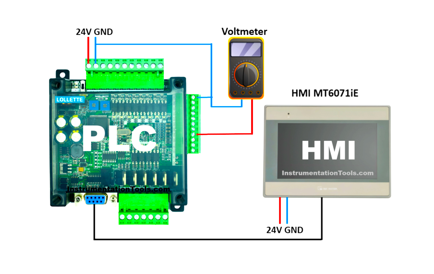
Preparation:
- Supply 24V DC power to the PLC.
- Connect the PLC to the PC using a USB to Serial RS232 cable.
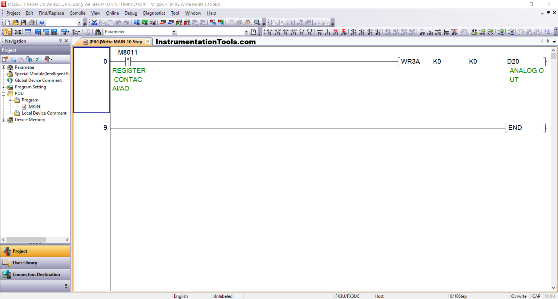
Write PLC Program
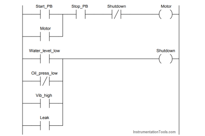
1. Create the PLC Program as Follows
Use the WR3A instruction with module setting “0/K0” and analog output address “0/K0”. The ANALOG OUT (D20) word memory is used to store analog output resolution data. The NO contact from REGISTER CONTACT AI/AO(M8011) bit memory is used to activate this instruction.
2. Check Device Connection
Verify the USB to Serial RS-232 adapter connection through Device Manager. For example, if detected at COM5 with these settings:
- Bit rate: 38.4 Kbps,
- Data bits: 7,
- Parity: Even,
- Stop bits: 1
Note: You can select the COM port number as per your system; the number may vary.
3. Configure Connection Parameters
In the software, open Connection Detection → Connection1 menu, then configure:
- Interface: Serial USB (RS-232C),
- COM Port: COM5,
- Transmission Speed/Baudrate: 38.4 Kbps,
- Setup: Parity Even, Data bits 7, Stop bits 1.
4. Click Connection Test. If successful, the message “Successfully Connected with the FX3U/FX3UC CPU” will appear.
5. Send the Program to the PLC.
Click Online → Write to PLC menu, select Parameter + Program, then press Execute.
Design HMI with EasyBuilder Pro
1. Power the HMI with 24Vdc. Connect the PC to HMI using a Mini USB Type B cable.
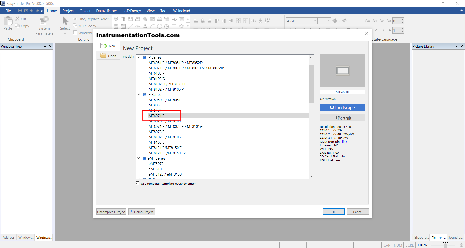
2. Create New Project
Open EasyBuilder Pro → Click [New], select HMI model [MT6071IE], then click [OK].
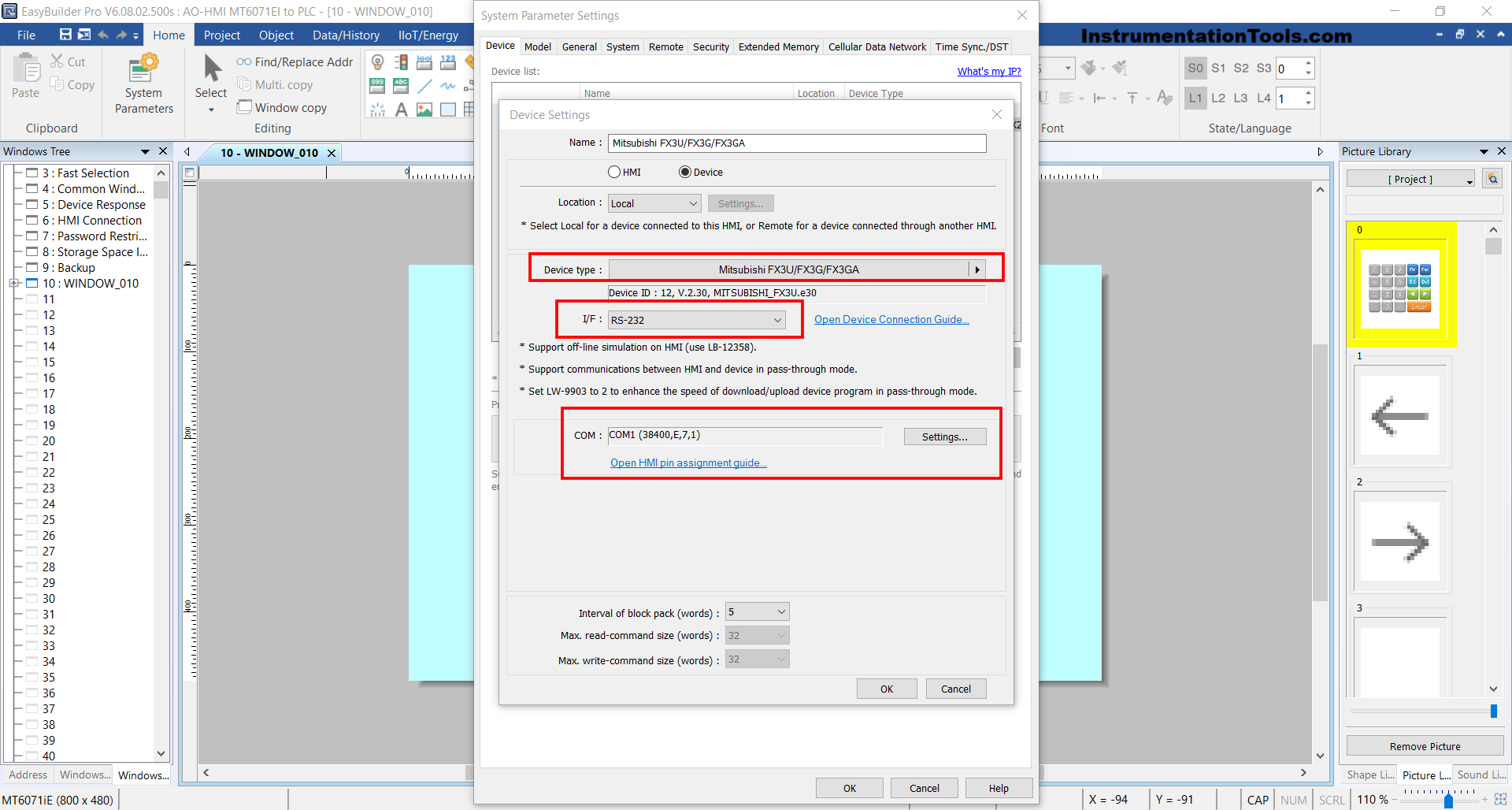
3. Add PLC Device
In the System Parameter window, click [New Device/Server], then configure:
- Port: RS-232COM: COM1(*)(38400,E,7,1)
- Device Type: Mitsubishi FX3U/FX3G/FX3GA
- Click [OK].
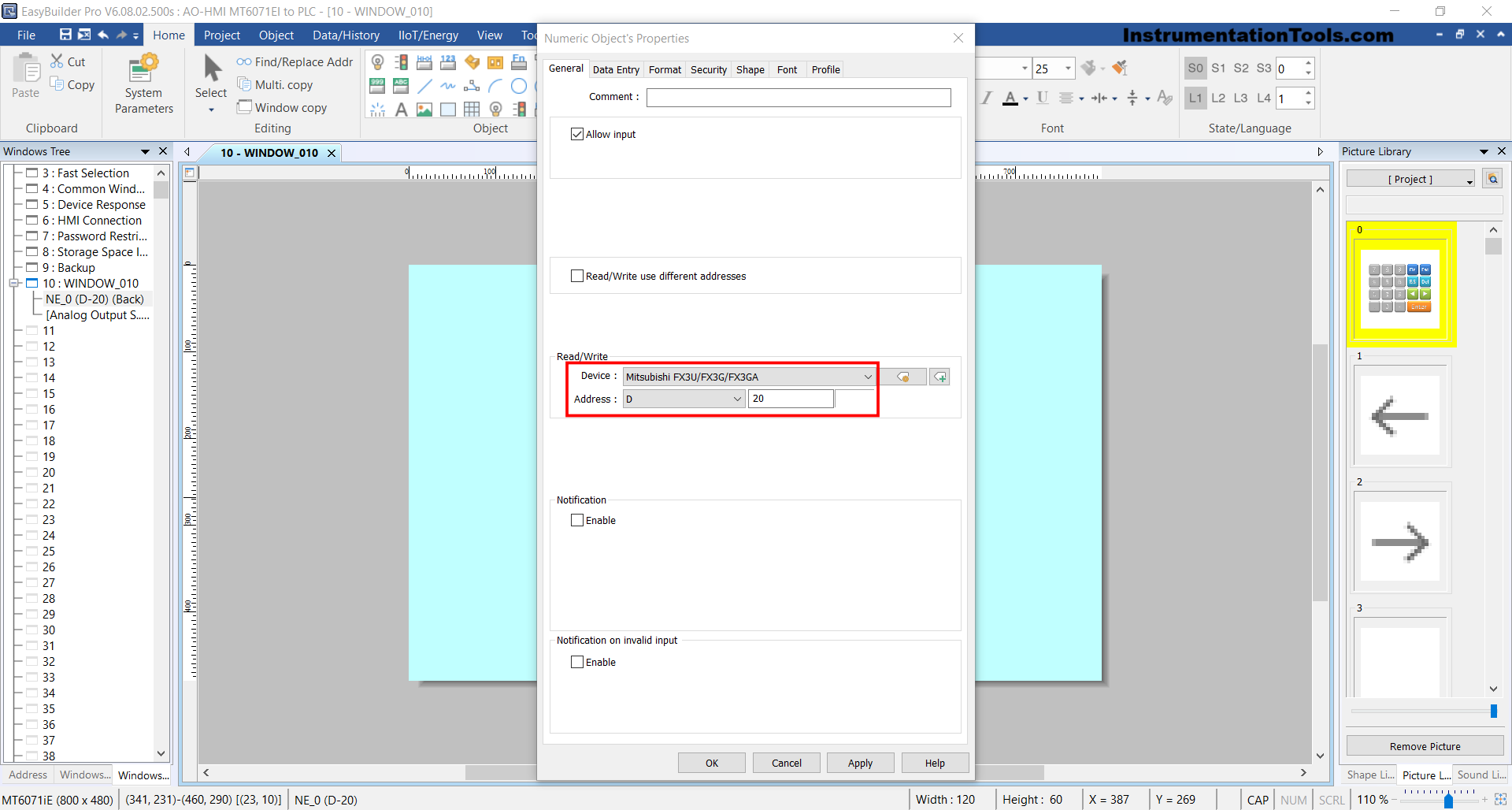
4. Design HMI Interface
Insert “Numeric Object” → Set Device to “Mitsubishi FX3U/FX3G/FX3GA” and word memory address “D20“, matching the Analog Output Resolution address in PLC.
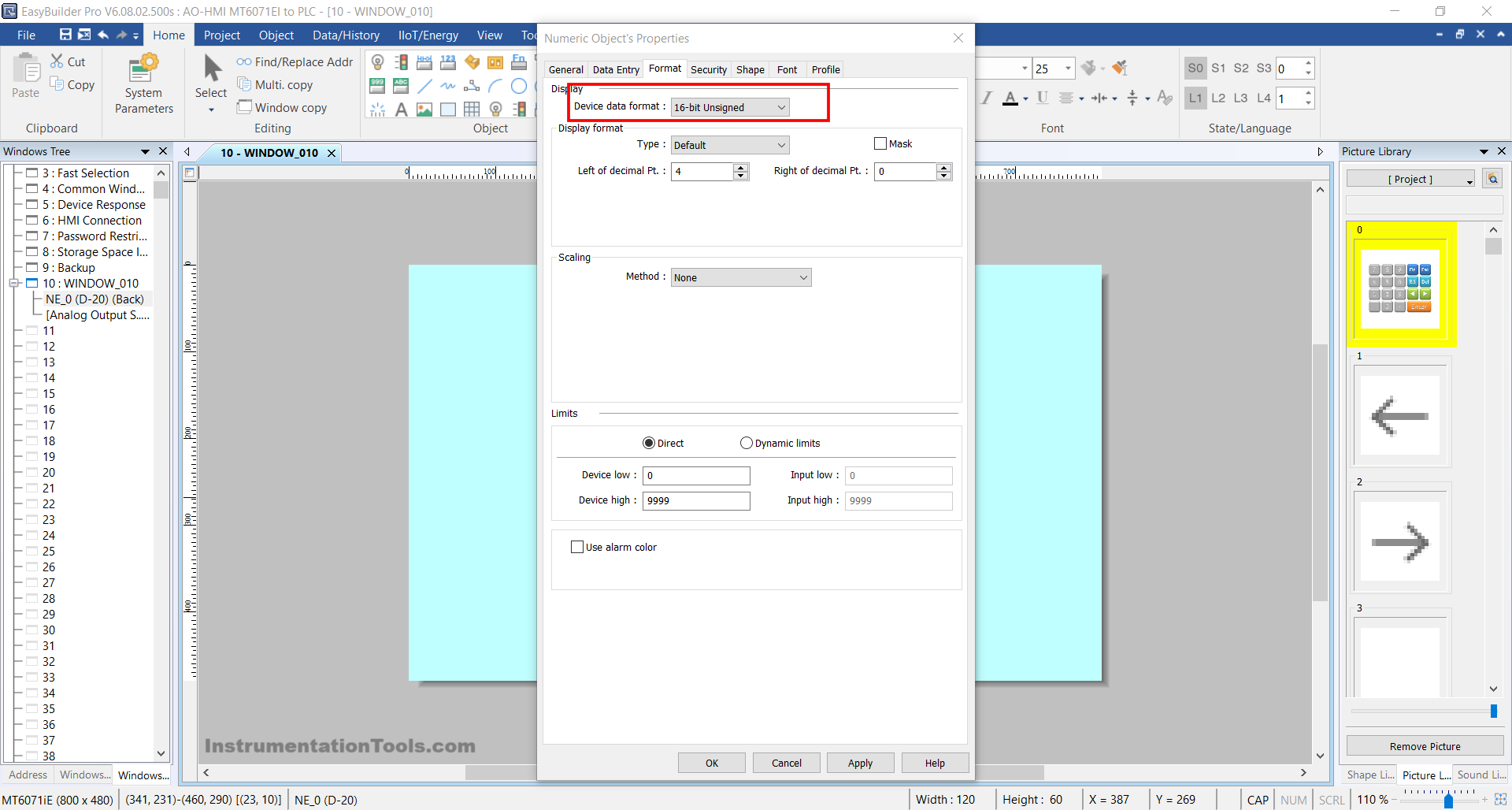
Set Data Format to “16-bit Unsigned“, then click [OK].
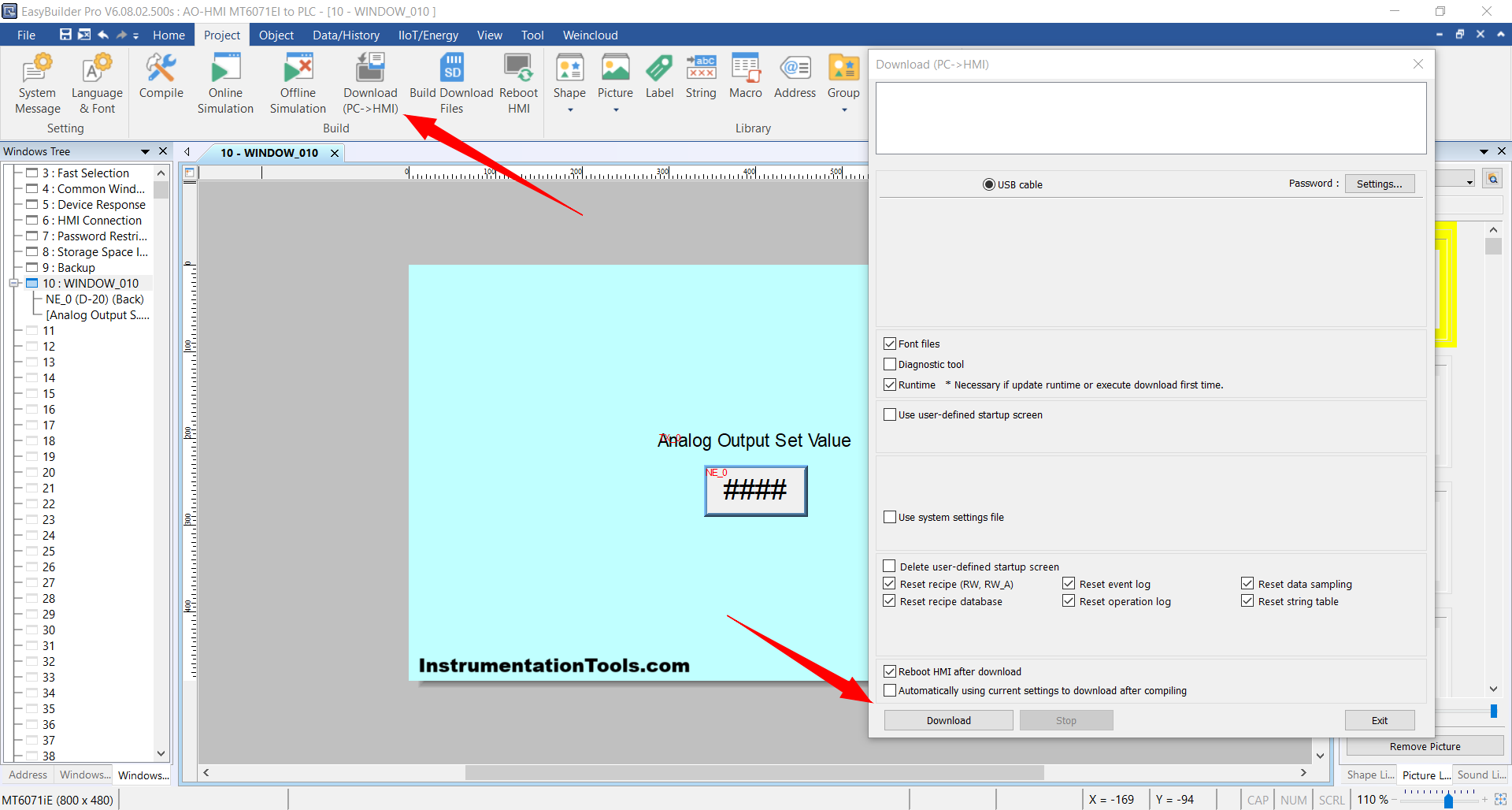
5. Transfer Design to HMI
Click menu [Project] → [Download(PC->HMI)].
6. Final Step
Disconnect the Mini USB Type B cable and connect the PLC to the HMI using a DB9 RS-232 Male to Female cable.
Read Next:
- Create an Application in HMI using Tia Portal
- Mitsubishi PLC + Weintek HMI: Analog Output
- About the SCADA and HMI Automation Systems
- PLC Programming for Industrial Oven Control
- PLC Ladder Logic for Garden Sprinkler System