This article will discuss an automatic filling system for two tanks using an Omron PLC. The purpose of this system is to provide hot and cold water in separate tanks. The heating and cooling processes can only be carried out when both tanks are filled to capacity. These processes will stop when there is no water in either of the tanks.
Program Objective
Steps for the Water Filling and Temperature Control System (Hot & Cold Water)
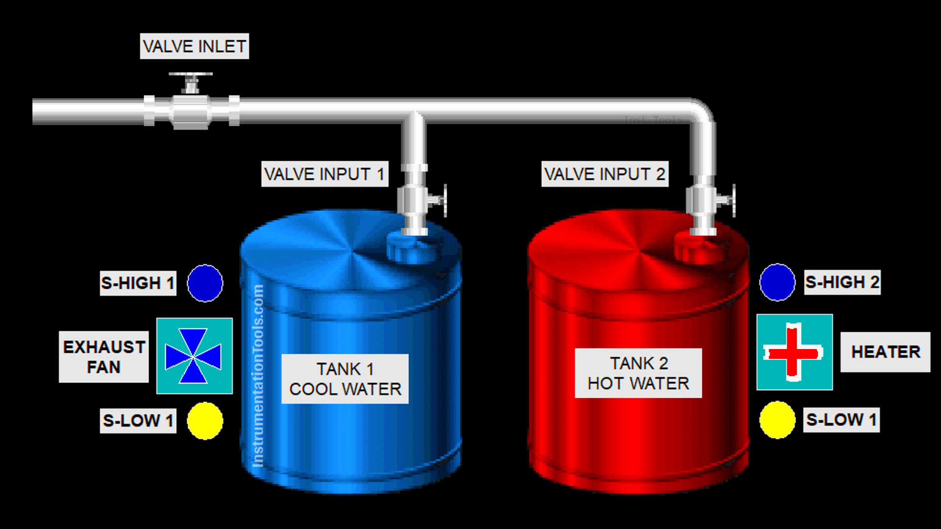
1. Dual Tanks with Shared Inlet Line:
- There are two tanks (Tank 1 & Tank 2) connected to a common water supply line.
- Each tank has an independent input valve to control the water flow.
- An inlet valve controls the main water flow before it splits into the individual input valves.
- The inlet valve will open when the system is started.
2. Individual Tank Functions:
- Tank 1: Stores cold water.
- Tank 2: Stores hot water.
3. Automatic Filling When Empty:
The system will begin automatic filling if:
- The initial condition shows that the tank is empty (below the minimum level), causing the input valve to Open.
- The filling process continues until the water level reaches its maximum.
- Once full, the input valve will close.
4. Heater & Cooling Fan Activation:
When the water reaches the full level:
- The heater in Tank 2 will turn on.
- The cooling fan in Tank 1 will turn on.
5. Operating Conditions for Heater & Fan:
The heater and cooling fan will only operate if:
- There is water inside the tank (they will not operate when the tank is empty).
Hot and Cold Water Tanks Process
IO Mapping
| S.No. | Comment | Input (I) | Output(Q) | Memory Bit |
|---|---|---|---|---|
| 1 | START | 0.00 | ||
| 2 | STOP | 0.01 | ||
| 3 | SENS_LOW_TANK1 | 0.02 | ||
| 4 | SENS_HIGH_TANK1 | 0.03 | ||
| 5 | SENS_LOW_TANK2 | 0.04 | ||
| 6 | SENS_HIGH_TANK2 | 0.05 | ||
| 7 | VALVE_INLET | 100.00 | ||
| 8 | VALVE_IN_TANK1 | 100.01 | ||
| 9 | EXHAUST_FAN | 100.02 | ||
| 10 | VALVE_IN_TANK2 | 100.03 | ||
| 11 | HEATER | 100.04 | ||
| 12 | SYSTEM_ON | W0.00 |
Omron PLC Program
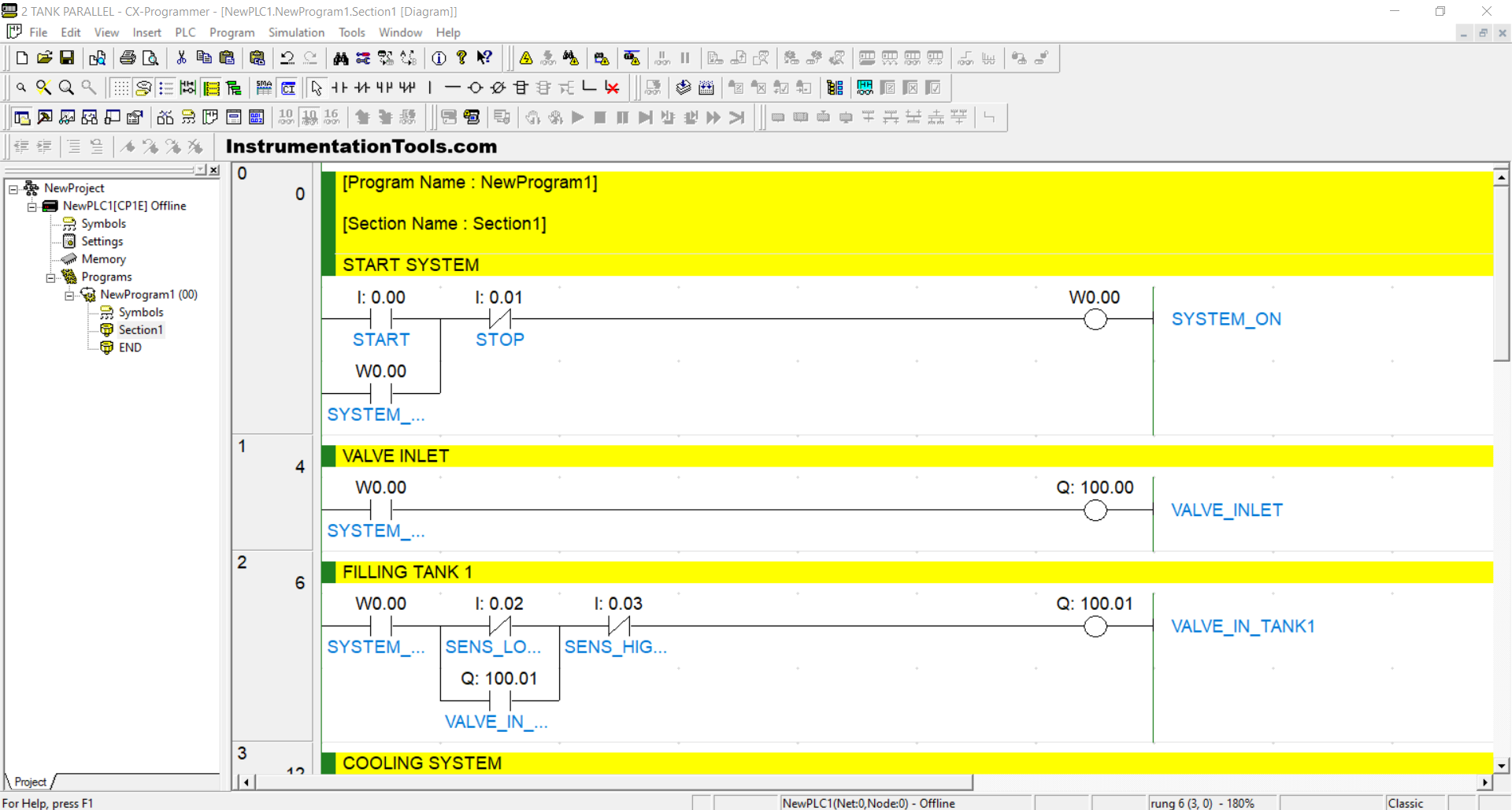
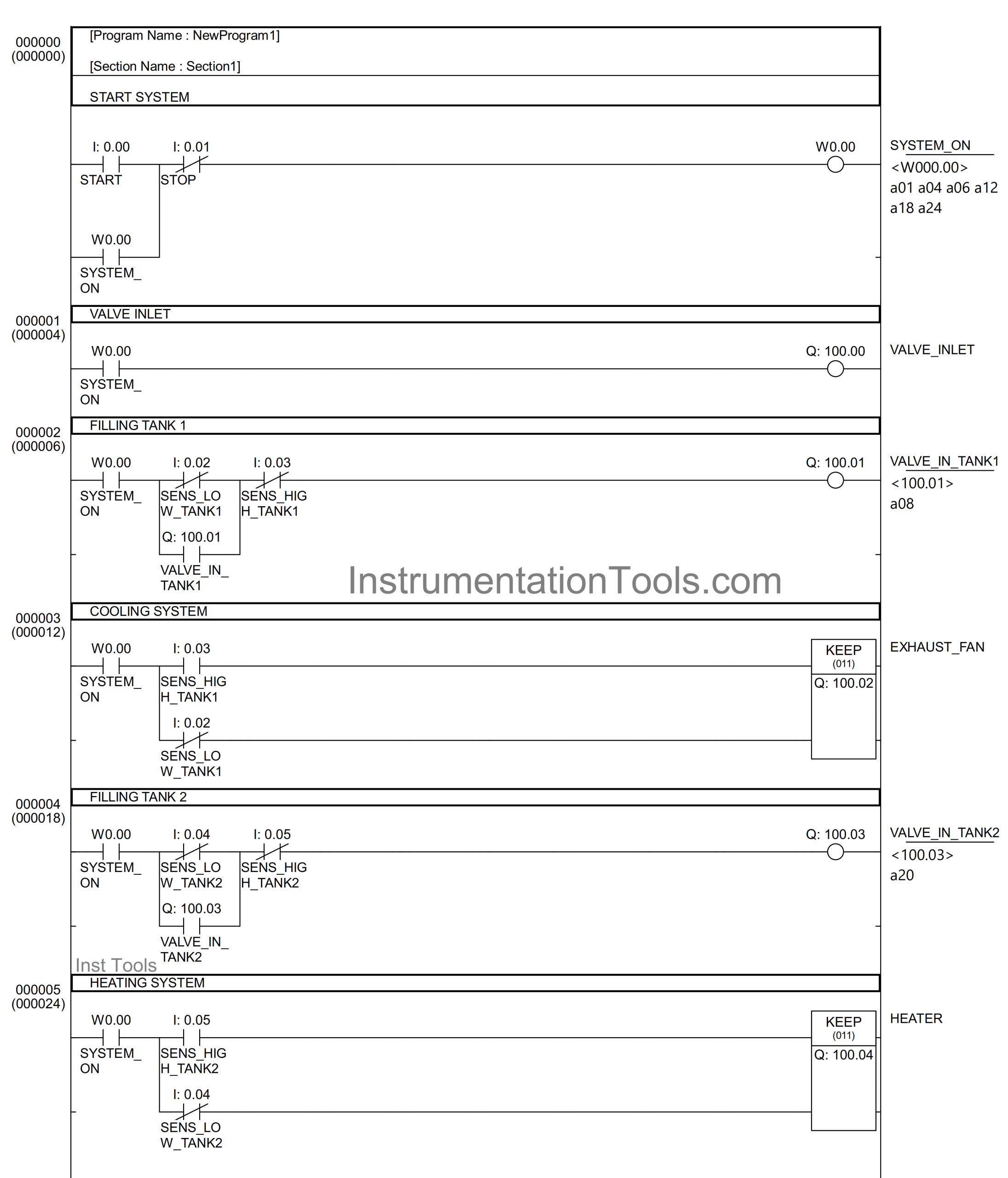
RUNG 0 (START SYSTEM)
In this Rung, if the START (0.00) button is pressed, the memory bit SYSTEM_ON (W0.00) will be in a HIGH state. Because it uses Latching, the memory bit SYSTEM_ON (W0.00) will remain in a HIGH state even though the START (0.00) button has been released.
The memory bit SYSTEM_ON (W0.00) will be in a LOW state if the STOP (0.01) button is pressed.
RUNG 1 (VALVE INLET)
In this Rung, if the NO contact of the memory bit SYSTEM_ON (W0.00) is in a HIGH state, then the VALVE_INLET (100.00) output will be OPEN.
The VALVE_INLET (100.00) output will be CLOSED if the NO contact of the memory bit SYSTEM_ON (W0.00) has returned to a LOW state.
RUNG 2 (FILLING TANK 1)
When the NO contact of the memory bit SYSTEM_ON (W0.00) is in the HIGH state and the NC contact of the SENS_LOW_TANK1 (0.02) and SENS_HIGH_TANK1 (0.03) sensors are in the LOW state, the VALVE_IN_TANK1 (100.01) output will be OPEN.
Because it uses Latching, the VALVE_IN_TANK1 (100.01) output will remain OPEN even though the NC contact of the SENS_LOW_TANK1 (0.02) sensor is in the HIGH state.
The VALVE_IN_TANK1 (100.01) output will be closed when the NC contact of the SENS_HIGH_TANK1 (0.03) sensor is in the HIGH state.
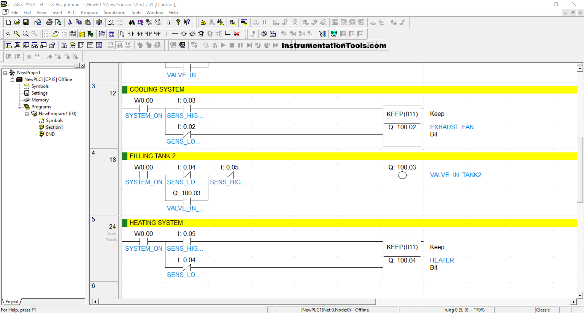
RUNG 3 (COOLING SYSTEM)
In this Rung, the EXHAUST_FAN (100.02) output will be ON if the NO contact of the memory bit SYSTEM_ON (W0.00) and the SENS_HIGH_TANK1 (0.03) sensor, and the NC contact of the SENS_LOW_TANK1 (0.02) sensor are in the HIGH state.
The EXHAUST_FAN (100.02) output will be OFF when the NO contact of the SENS_HIGH_TANK1 (0.03) sensor and the NC contact of the SENS_LOW_TANK1 (0.02) sensor are in the LOW state.
RUNG 4 (FILLING TANK 2)
When the NO contact of the memory bit SYSTEM_ON (W0.00) is in the HIGH state and the NC contact of the SENS_LOW_TANK2 (0.04) and SENS_HIGH_TANK2 (0.05) sensors are in the LOW state, the VALVE_IN_TANK2 (100.03) output will be OPEN.
Because it uses Latching, the VALVE_IN_TANK2 (100.03) output will remain OPEN even though the NC contact of the SENS_LOW_TANK2 (0.04) sensor is in the HIGH state.
The VALVE_IN_TANK2 (100.03) output will be CLOSED when the NC contact of the SENS_HIGH_TANK2 (0.05) sensor is in the HIGH state.
RUNG 5 (HEATING SYSTEM)
In this Rung, the HEATER (100.04) output will be ON if the NO contact of the memory bit SYSTEM_ON (W0.00) and the SENS_HIGH_TANK2 (0.05) sensor, and the NC contact of the SENS_LOW_TANK2 (0.04) sensor are in the HIGH state.
The HEATER (100.04) output will be OFF when the NO contact of the SENS_HIGH_TANK2 (0.05) sensor and the NC contact of the SENS_LOW_TANK2 (0.04) sensor are in the LOW state.
Read Next:
- PLC Program for Temperature Control
- PLC Logic for Continuous Filling Operation
- Product Painting PLC Program using Omron
- PLC Program for Loss in Weight Liquid Systems
- Baking with Auto and Manual Modes PLC Logic