This article will discuss the use of Timer On Delay (TON) and Timer Off Delay (TOFF) in the XG-5000 PLC software. A TON timer is a type of timer that starts counting down after its input becomes active (ON). Once the predetermined time (preset time) is reached, the timer’s output becomes active (ON). A TOFF timer is the opposite of a TON timer. A TOFF timer starts counting down after its input becomes inactive (OFF). During the preset time, the output remains active, and after the preset time is reached, the output becomes inactive.
Program Objective
TON Timers Sequence:
- This sequence of TON Timers will start when triggered by the Button.
- After receiving the trigger, Lamp-1 will turn ON, and Timer On Delay-1 will start counting.
- After Timer On Delay-1 has finished counting, Lamp-1 will be OFF and Lamp-2 will be ON.
- Next, with Timer On Delay-2, start counting.
- After Timer On Delay-2 has finished counting, Timer On Delay-1 will be reset.
- The system will continue to repeat until the Stop button is Pressed.
TOFF Timers Sequence:
- This sequence of TOFF Timers will start when triggered by the Button.
- After receiving a momentary trigger, Timer Off Delay-1 starts counting.
- Lamp-3 will turn ON according to the countdown time of Timer Off Delay-1.
- After Timer Off Delay-1 has finished counting, Lamp-3 will be OFF.
- Next, Timer Off Delay-2 will be triggered momentarily and start counting.
- Lamp-4 will light up according to the countdown time of Timer Off Delay-2.
- After Timer Off Delay-2 has finished counting, Timer Off Delay-1 will be triggered again.
- The system will continue to repeat until the Stop button is Pressed.
The preset time value for each timer can be set as desired.
Practical Example of TON and TOFF Timers
IO Details
| S.No. | Comment | Input (I) | Output(Q) | Memory Bit | Memory Word | Timer |
| 1 | START | P0000 | ||||
| 2 | STOP | P0001 | ||||
| 3 | TRIGGER_TON | P0002 | ||||
| 4 | TRIGGER_TOFF | P0003 | ||||
| 5 | LAMP_1 | P0040 | ||||
| 6 | LAMP_2 | P0041 | ||||
| 7 | LAMP_3 | P0042 | ||||
| 8 | LAMP_4 | P0043 | ||||
| 9 | TIMER1 | T000 | ||||
| 10 | TIMER2 | T001 | ||||
| 11 | TIMER3 | T002 | ||||
| 12 | TIMER4 | T003 | ||||
| 13 | SV_TIMER1 | D0000 | ||||
| 14 | SV_TIMER2 | D0001 | ||||
| 15 | SV_TIMER3 | D0002 | ||||
| 16 | SV_TIMER4 | D0003 | ||||
| 17 | SYSTEM_ON | M0000 | ||||
| 18 | IR_TON | M0001 |
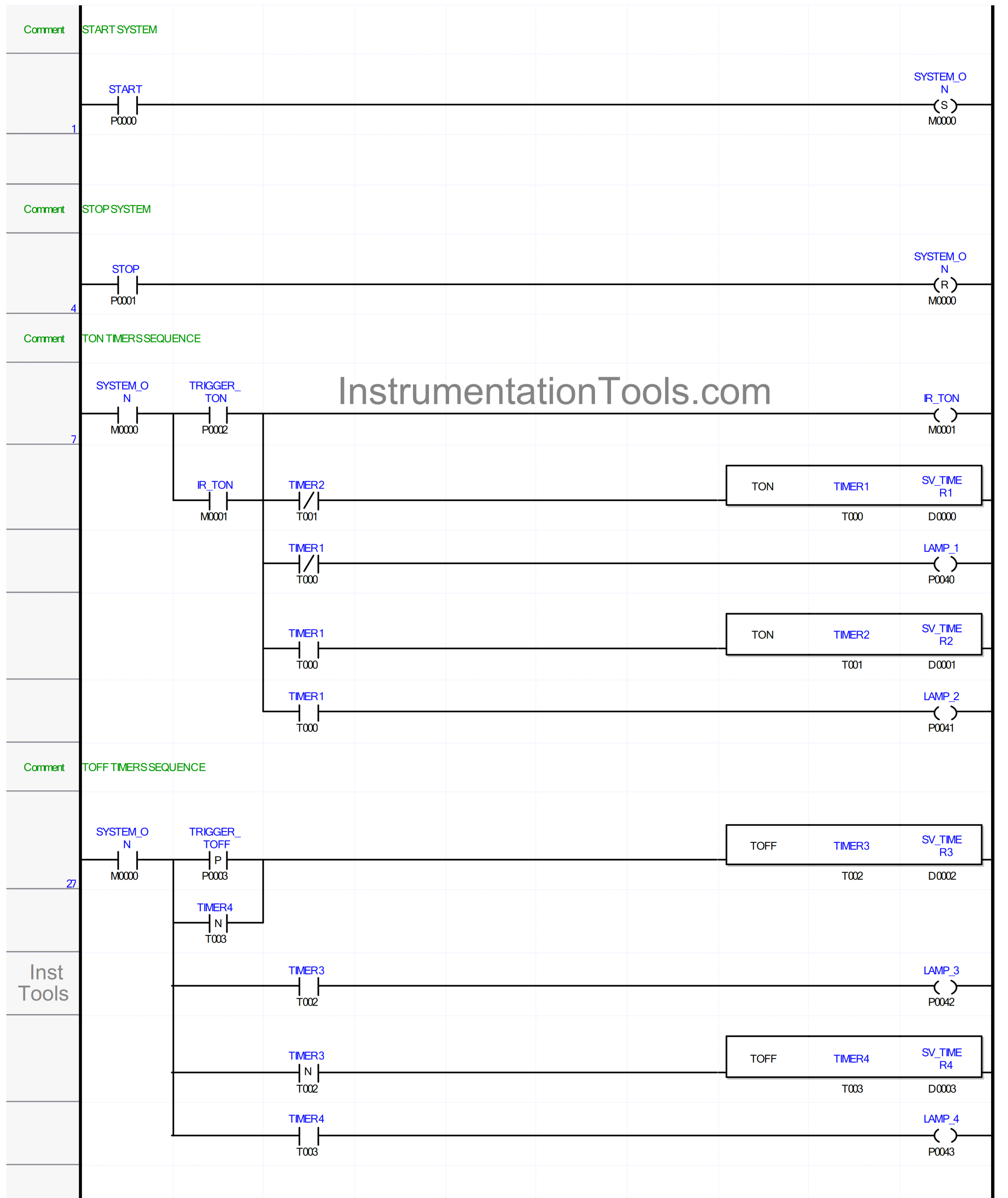
Timers Program
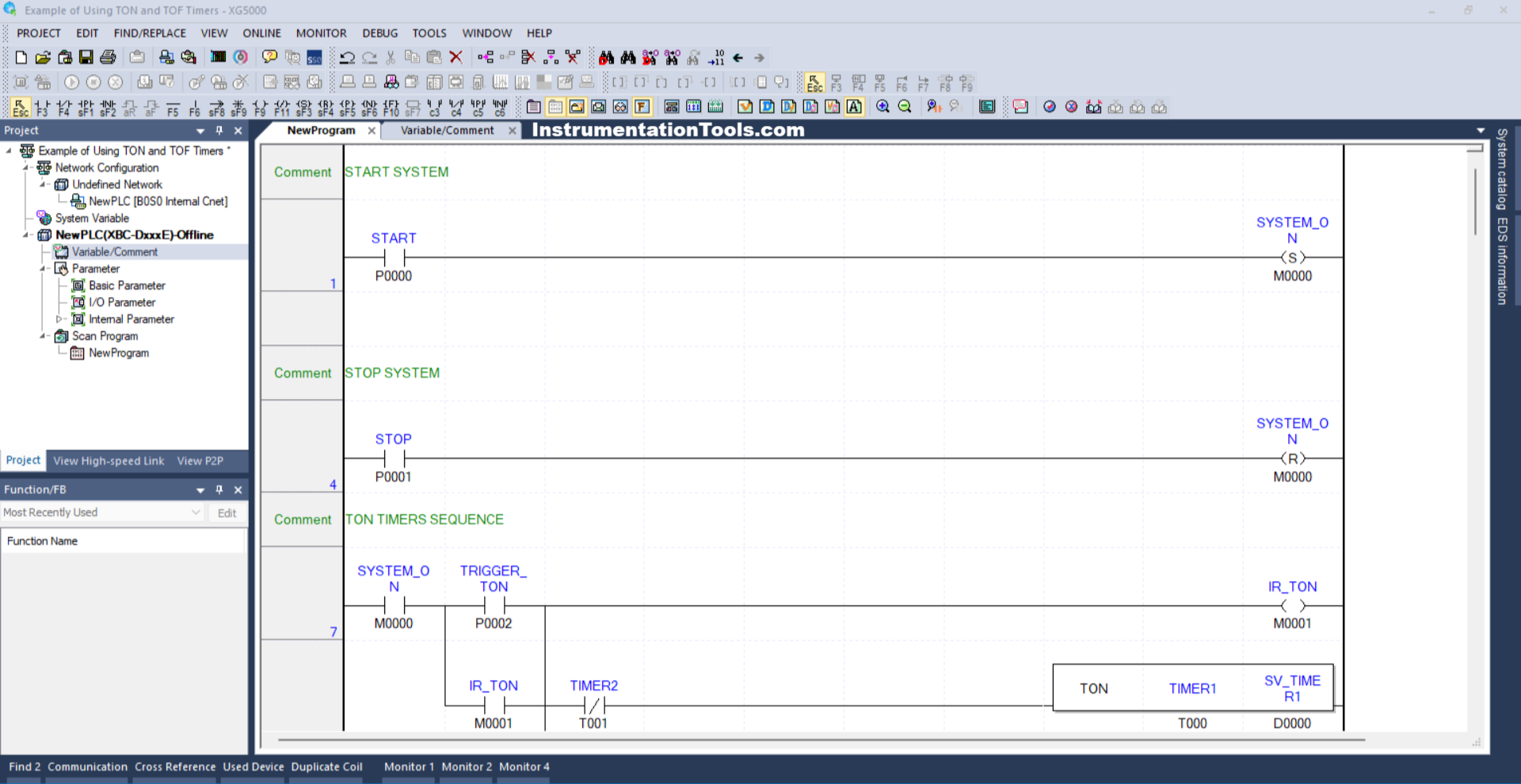
RUNG 1 (START SYSTEM)
In this Rung, the memory bit SYSTEM_ON (M0000) will be in the HIGH state when the START (P0000) button is Pressed. Because it uses the SET Coil Instruction, the memory bit SYSTEM_ON (M0000) will remain in the HIGH state even though the START (P0000) button has been Released.
RUNG 4 (STOP SYSTEM)
In this Rung, the memory bit SYSTEM_ON (M0000) will be in the LOW state if the STOP (P0001) button is Pressed. Because it uses the RESET Coil Instruction, the memory bit SYSTEM_ON (M0000) will remain in the HIGH state even though the STOP (P0001) button has been Released.
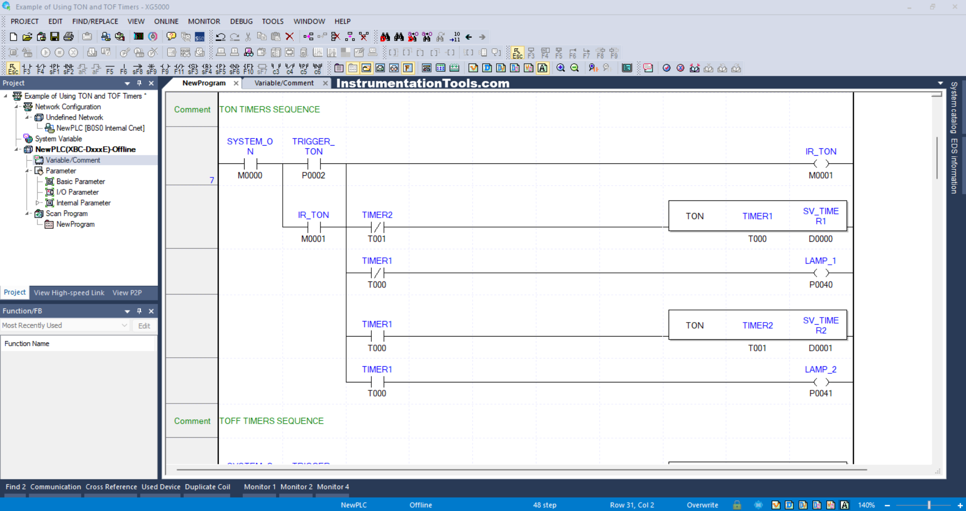
RUNG 7 (TON TIMERS SEQUENCE)
In this Rung, when the NO contact of memory bit SYSTEM_ON (M0000) in the HIGH state and the TRIGGER_TON (P0002) Button is Pressed, the memory bit IR_TON (M0001) will be in the HIGH state, the LAMP_1 (P0040) output will be ON and the Timer TIMER1 (T000) start counting.
Because it uses Latching, the memory bit IR_TON (M0001) will remain in the HIGH state even though the TRIGGER_TON (P0002) Button has been Released.
Once Timer TIMER1 (T000) has finished counting, the output LAMP_1 (P0040) will become OFF, the output of LAMP_2 (P0041) will become ON, and Timer TIMER2 (T001) will start counting.
When Timer TIMER2 (T001) has finished counting, Timer TIMER1 (T000) will be reset due to the interlock of Timer TIMER2 (T001).
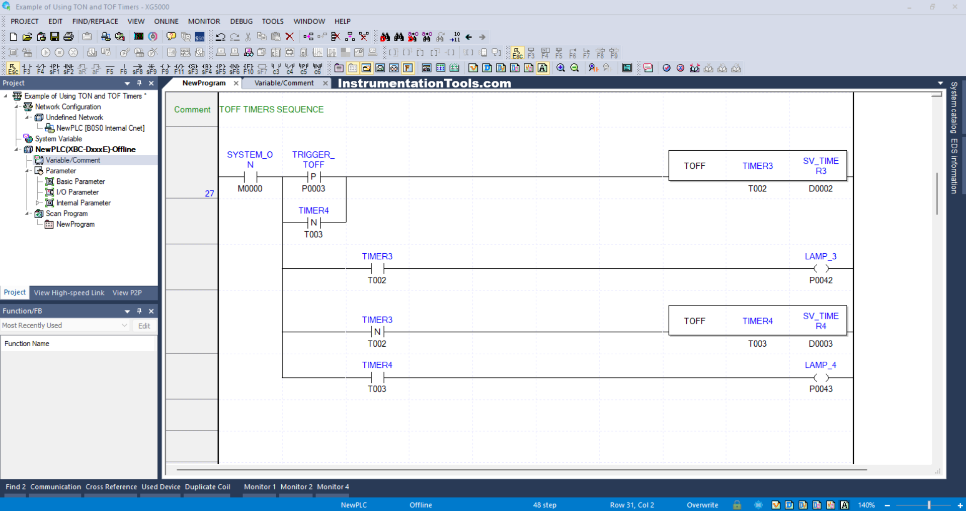
RUNG 27 (TOFF TIMERS SEQUENCE)
In this Rung, when the NO contact of memory bit SYSTEM_ON (M0000) in the HIGH state and the TRIGGER_TOFF (P0003) Button is Pressed, the Timer TIMER3 (T002) starts counting.
Because the TRIGGER_TOFF (P0003) Button uses a Positive Transition-Sensing Contact type NO contact, the TIMER3 (T002) Timer will get a Trigger momentarily when conditions change from LOW to HIGH state of the TRIGGER_TOFF (P0003) Button.
The output LAMP_3 (P0042) will be ON when the NO contact of the TIMER3 (T002) Timer is in the HIGH state.
Next, TIMER4 (T003) will start counting when it gets a Trigger from the NO Timer contact TIMER3 (T002).
Because the TIMER3 (T002) Timer uses a Negative Transition-Sensing Contact type NO contact, the TIMER4 (T003) Timer will get a Trigger momentarily when conditions change from the HIGH to LOW state of the Timer TIMER3 (T002) NO contact.
The output LAMP_4 (P0043) will be ON when the NO contact of Timer TIMER4 (T003) is in the HIGH state.
When Timer TIMER4 (T003) has finished counting, it will give a Trigger momentarily to Timer TIMER3 (T002).
Read Next:
- Edge Detection in PLC Programming
- Ladder Logic Example with Timers
- Motor Control Start & Stop Timer Circuit
- Electrical Panel Door Earth Bonding
- PLC Programming Example on Timers