In this post, we will see how to assign values to a tag. This is similar to writing instruction in any language. In the earlier posts, we saw some basic rules on how to assign a value to a tag. Here, we will dive into some more syntax which can be explored in SCL language and used. Once you are through with the syntax of expressions having value assignments, you can then write any statement properly without any error.
Value Assignments in SCL Language
To those who do not know what a value assignment is, let us recall our earlier study. It is a statement which corresponds to a writing instruction. The general syntax is tag1 := tag2;. The left hand side of := is the tag where value will be written. The right hand side of := is the tag from which the value will be read and written. The right hand side can either be a tag or a constant. A semicolon is required in the end to terminate the statement. Let us now have a look at the various types of value assignment statements.
Single value statements
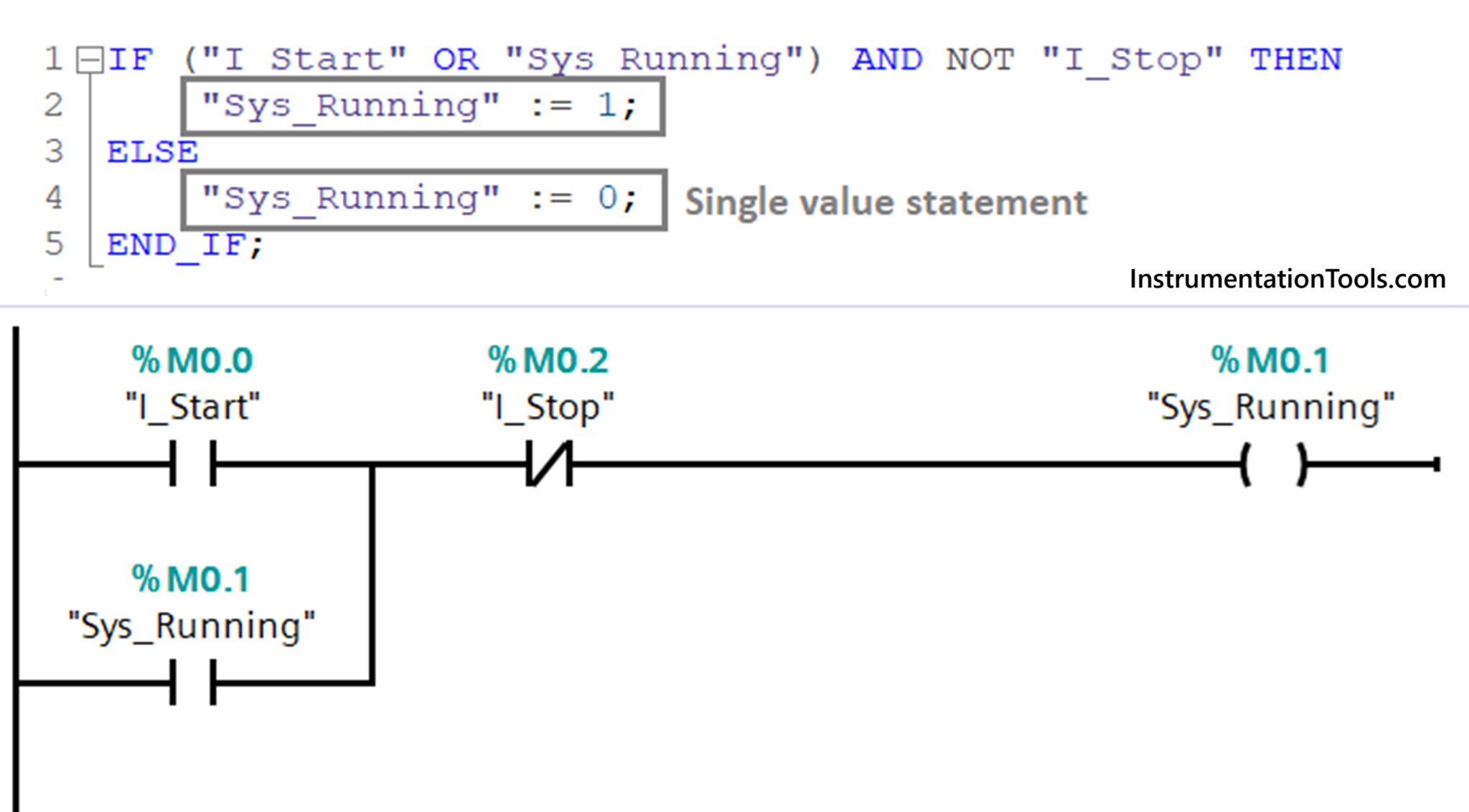
The very first example we saw now is a single value statement. In this, the right hand side of := contains a tag, constant or an expression, and the value is written to a single tag on the left hand side. That is why the name is a single value statement. Refer to the above image for more understanding. As seen in the ladder logic above, a single tag of sys_running is being written. So, in the SCL language, we too write a single statement where either a 1 or 0 is moved in the tag of sys_running.
Multiple value statements
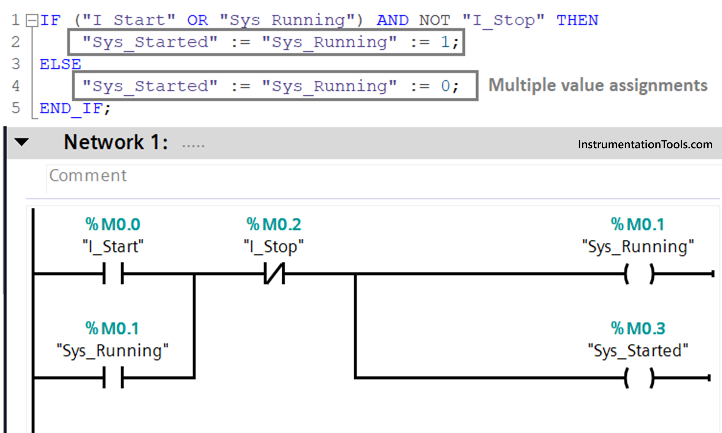
In this, the right hand side of := contains a tag, constant or an expression, and the value is written to multiple tags on the left hand side. Means, the data to be read will be written to more than one tag. That is why the name is a multiple value statement. Refer to the above image for more understanding. As seen in the ladder logic above, two tags of sys_running and sys_started are being written. So, in the SCL language, we too write a single statement where either a 1 or 0 is moved in both the tags of sys_running and sys_started.
The general syntax is tag1 := tag2 := tag3;. Here, the data flow starts from the right hand side and moves towards the left hand side. For this reason, multiple := are used to declare the statement as valid. The value of tag3 or the third expression is written to tag2 or the second expression. The value of tag2 or the second expression is written to tag1 or the first expression.
Combined value statements
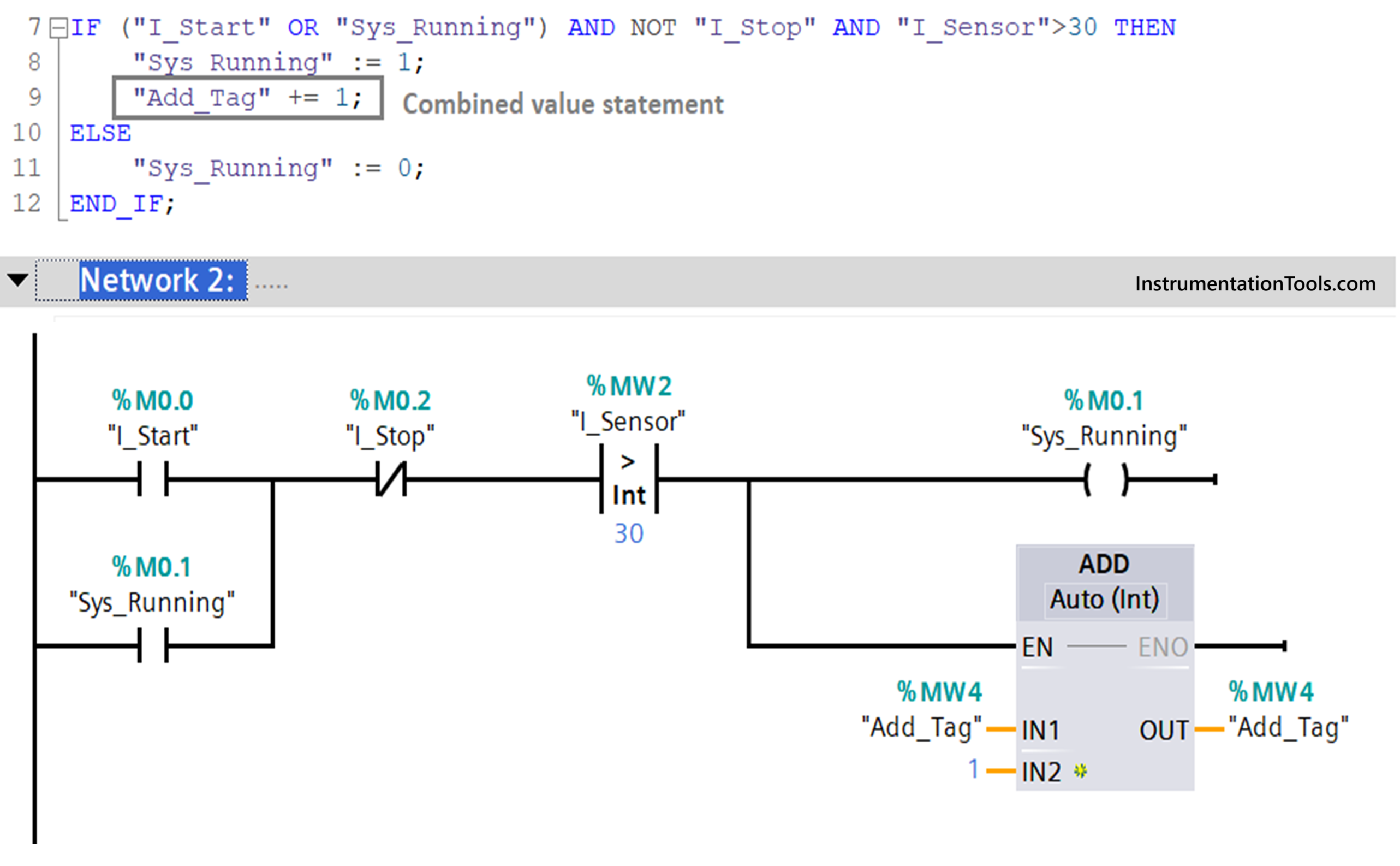
This is a very powerful tool which makes the TIA portal software very friendly to use. In this, you can combine the operators like +, – , * etc. with = or the assignment operator. Due to this, your code size reduces and you can create various shortcuts in the logic for minimising the memory consumption of the CPU.
The general syntax is tag1 += tag2;. The left hand side of += is the tag where the value will be written. The right hand side of += is the tag from which the value will be read and written. But here, the actual meaning of this syntax is – tag2 is added with tag1, and the result is written in tag1. So, in the other way, you could have written this in a single value style like – tag1 := tag1 + tag2;. This syntax too has the same meaning, but we reduced the coding here using combined value style.
As seen in the ladder logic above, we have added add_tag with itself to 1, and the result is written in add_tag. So, in the SCL language, we have written the same thing as – Add_tag +=1; One thing to note is that you can write combined style for either single value or multiple values. This makes value assignment very sharp and efficient to use in SCL language.
In the next post, we will see some general rules for writing a program in SCL language.
Read Next:
- PLC Instruction List Program for Basic Instructions
- How to do Scaling for Analog Input in RSLogix 500?
- Standard Colors used in the PLC Automation Systems
- Structured Text vs. Instruction List for PLC Programming
- Advanced Skills Required for a PLC Programmer to Get a Job