Inst ToolsInst ToolsInst Tools
  • Courses
  • Automation
    • PLC
    • Control System
    • Safety System
    • Communication
    • Fire & Gas System
  • Instrumentation
    • Design
    • Pressure
    • Temperature
    • Flow
    • Level
    • Vibration
    • Analyzer
    • Control Valve
    • Switch
    • Calibration
    • Erection & Commissioning
  • Interview
    • Instrumentation
    • Electrical
    • Electronics
    • Practical
  • Q&A
    • Instrumentation
    • Control System
    • Electrical
    • Electronics
    • Analog Electronics
    • Digital Electronics
    • Power Electronics
    • Microprocessor
  • Request
Search
  • Books
  • Software
  • Projects
  • Process
  • Tools
  • Basics
  • Formula
  • Power Plant
  • Root Cause Analysis
  • Electrical Basics
  • Animation
  • Standards
  • 4-20 mA Course
  • Siemens PLC Course
Reading: PLC Light Sequence Control using Bit Shift Registers
Share
Notification Show More
Font ResizerAa
Inst ToolsInst Tools
Font ResizerAa
  • Courses
  • Design
  • PLC
  • Interview
  • Control System
Search
  • Courses
  • Automation
    • PLC
    • Control System
    • Safety System
    • Communication
    • Fire & Gas System
  • Instrumentation
    • Design
    • Pressure
    • Temperature
    • Flow
    • Level
    • Vibration
    • Analyzer
    • Control Valve
    • Switch
    • Calibration
    • Erection & Commissioning
  • Interview
    • Instrumentation
    • Electrical
    • Electronics
    • Practical
  • Q&A
    • Instrumentation
    • Control System
    • Electrical
    • Electronics
    • Analog Electronics
    • Digital Electronics
    • Power Electronics
    • Microprocessor
  • Request
Follow US
All rights reserved. Reproduction in whole or in part without written permission is prohibited.
Inst Tools > Blog > PLC Tutorials > PLC Light Sequence Control using Bit Shift Registers

PLC Light Sequence Control using Bit Shift Registers

Master the concept of PLC Light Sequence Control and see how bit shift registers optimize coding in automation applications.

Last updated: March 11, 2025 4:35 pm
Viral Nagda
PLC Tutorials
No Comments
Share
7 Min Read
SHARE

Bit shift registers are a very interesting concept in PLC programming. It is specially used in moving applications and reduces overall coding to a great extent. As the complexity of the program increases, means must be achieved eventually to simplify them, and bit shift registers play a very important role here. We will write a very simple logic in this post using bit shift registers to understand it more properly. For that, Studio 5000 software and ladder logic programming will be used.

PLC Light Sequence Control

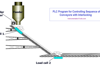
  1. Let us understand the case scenario first. Refer to the below image. We have a conveyor which is used to move the jars. The conveyor runs and stops every 2 seconds. There are a total of 8 slots in the conveyor (corresponding to bit numbers 0-7 as shown). There are 2 sensors in the incoming line – sensor-1 to sense short jars and sensor-2 to sense tall jars. Whenever a short jar is sensed, we have to store it in our memory and when that particular jar reaches slot number 3 (bit number-2), a brown lamp will turn on to indicate the presence of a short jar in the line. Whenever a tall jar is sensed, we have to store it in our memory and when that particular jar reaches slot number 7 (bit number-6), a pink lamp will turn on to indicate the presence of a tall jar in the line. When the short jar has reached the last position after slot-8, a dark purple lamp will turn on to show that it has been thrown out of the conveyor. When the tall jar has reached the last position after slot-8, a light purple lamp will turn on to show that it has been thrown out of the conveyor. The sequence of jars will continue from incoming in line, and the short and tall jars will be sensed to turn on the required lamps.
PLC Light Sequence Control using Bit Shift Registers
  1. To write this program, we will use Studio 5000 software here and write the coding in ladder logic language. Following are the PLC inputs – sensor-1 and sensor-2. Following are the PLC outputs – brown lamp for short jar, pink lamp for tall jar, dark purple lamp for short jar and light purple lamp for tall jar.
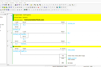
  2. Let us write the logic now by referring to the image below. The first two rungs are used to turn on and off the conveyor every 2 seconds. In the first rung, the conveyor remains on for 2 seconds and after that, the conveyor remains off for 2 seconds as in the second rung.
Bit Shift Registers PLC Program
  1. The third and fourth rungs are used to code bit shift registers left. As the name suggests, a bit is shifted left by one bit on every trigger. Let us understand one BSL instruction. It has four inputs – array, control, source bit and length. The array contains the data that is to be modified and shifted. The control contains the data showing all the internal status of the BSL executing. The source bit contains the tag which writes 1 or 0 in the data present in the array. It is written in bit number 0 of the array tag. The length specifies the number of bits that will be shifted. Bits after that number will be ignored in the execution of BSL. To shift the bit, the BSL instruction must be triggered (here, we trigger when the conveyor is off as written.)
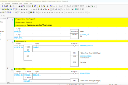
  2. Let us see the first BSL instruction. Refer to the below image. When the bit convy_on_time_over is on, the BSL instruction is executed once and bits are shifted from 0th to 7th position in every trigger. The value of bit 0 is determined by jar sensor-1. So, when a short jar is sensed, a 1 is written and when the jar is not sensed, a 0 is written. You can see the watch window on the left side, where currently, the data has shifted to bit number 1 when I took the snapshot. The same thing works for the second BSL instruction, which is modified by jar sensor-2.
Studio 5000 software program
  1. In the fourth rung, when the data of 1 has shifted to bit number 2 (slot number 3), the brown color lamp turns on. So, whenever a 1 is present in the sequence and it has reached that bit position, the lamp will turn on. In the fifth rung, when the data of 1 has shifted to bit number 6 (slot number 7), the pink color lamp turns on. So, whenever a 1 is present in the sequence and it has reached that bit position, the lamp will turn on.
  2. Now, the BSL control data has an output bit named UL or unload. As per our requirement, we need to turn on the purple lamps after the jar has reached the outlet and left slot number 8. So, when the UL bit of short lamp BSL is on, the dark purple lamp turns on and when the UL bit of tall lamp BSL is on, the light purple lamp turns on. The UL is used to store the value of the bit after the length has been achieved (in our case, it is bit number 8 as the length is 8 starting from 0 to 7).

In this way, we saw how to write a PLC program for controlling light sequences using bit shift registers.

Read Next:

  • PLC Instruction List Example for Level Control
  • Motor Direction Control using Limit Switches
  • Star Delta Starter using Functional Block Diagram
  • While Do Statement in Structured Text PLC Program
  • PLC Instruction List for Motor Reverse and Forward
Don't Miss Our Updates
Be the first to get exclusive content straight to your email.
We promise not to spam you. You can unsubscribe at any time.
Invalid email address
You've successfully subscribed !

Continue Reading

What is a Tag? Types of Tags in SCADA
PLC Programming for Traffic Barrier Control
Conveyor Sorting Machine PLC Program with Calculation Function
PLC Instruction List Example for Level Control of Tank
Free Download Programmable Logic Controller (PLC) Book
What is PLC Redundancy?
Share This Article
Facebook Whatsapp Whatsapp LinkedIn Copy Link
Share
Leave a Comment

Leave a Reply Cancel reply

Your email address will not be published. Required fields are marked *

Stay Connected

128.3kFollowersLike
69.1kFollowersFollow
210kSubscribersSubscribe
38kFollowersFollow

Categories

Explore More

How to Start Writing SCL Language in Siemens Tia Portal?
Types of Cables used in Industrial Automation
Difference between DCS & PLC Systems
Difference Between FC and FB in Tia Portal
PLC Digital Input and Digital Output Modules
PLC Programming Example on Multi-Motor Control for Beginners
OB1 – Main Cyclic Organization Block in TIA Portal
How to Choose the Right Industrial Automation Solution?

Keep Learning

Wonderware Recipe Manager Plus

What is Recipe Management in SCADA?

Difference Between Wifi and Industrial Wireless

Difference Between Wifi and Industrial Wireless

Introduction to Schneider PLC

Different Types of Schneider PLC

Quiz Program Logic Using PLC Programming

Quiz Program Logic Using PLC Programming

Conveyor Control with Main Motor and Backup Motor

Conveyor Operation with a Backup Motor using PLC Ladder Diagram

Contextual HMI

What is Contextual HMI? – HMI Screens on a Mobile or Tablet

PLC Program for Temperature Control using Thermostat

PLC Program for Temperature Control using Thermostat

What is meant by a SCADA System

Troubleshoot the Status of a PLC Via CPU Indicators

Learn More

Creating Logic in Intouch Using Scripting

Create Logic with InTouch Scada using Scripting

Door Lock with Delay PLC Exercise Problems

Door Lock with Delay PLC Exercise Problems

2-way solenoid valve Normally Closed

What is a 2-way Solenoid Valve ?

Intrinsic Safety of Instruments

Intrinsic Safety of Instruments

proximitor module

Bently Nevada Vibration System Verification Procedure

Manual Call Point Testing Procedure

Manual Call Point Testing Procedure

Field Instruments enclosures

Pressure Transmitter Heated Enclosures

Pneumatic Valves and Cylinders Sizing

Pneumatic Valves and Cylinders Sizing – Part 1

Menu

  • About
  • Privacy Policy
  • Copyright

Quick Links

  • Learn PLC
  • Helping Hand
  • Part Time Job

YouTube Subscribe

Follow US
All rights reserved. Reproduction in whole or in part without written permission is prohibited.
Welcome Back!

Sign in to your account

Username or Email Address
Password

Lost your password?