Inst ToolsInst ToolsInst Tools
  • Ask
  • Courses
  • Videos
  • Q & A
    • Interview
      • Instrumentation
      • Electronics
      • Electrical
      • Practical Questions
    • MCQ
      • Instrumentation MCQ
      • Electrical MCQ
      • Electronics MCQ
      • Control Systems MCQ
      • Analog Electronics MCQ
      • Digital Electronics MCQ
      • Power Electronics MCQ
      • Microprocessor MCQ
      • Multiple Choice Questions
  • EE
    • Electronics
      • Electronics Q & A
      • Electronic Basics
      • Electronic Devices & Circuits
      • Electronics Animation
      • Digital Electronics
    • Electrical
      • Electrical Basics
      • Electrical Q & A
      • Power Electronics
      • Electrical Machines
      • Electrical Animation
      • Power Systems
      • Switchgear & Protection
      • Transmission & Distribution
  • Measure
    • Control Valves
    • Calibration
    • Temperature
    • Pressure
    • Flow
    • Level
    • Analyzers
    • Switches
    • Vibration
    • Solenoid Valve
  • Control
    • PLC Tutorials
    • Control Systems
    • Safety Instrumented System (SIS)
    • Communication
    • Fire & Gas System
  • More
    • Design
    • Tools
    • Animation
    • Basics
    • Formulas
    • Standards
    • TextBooks
    • Common
    • Software
    • Excel Tools
    • Erection & Commissioning
    • Process Fundamentals
    • Videos
    • Books
Search
All rights reserved. Reproduction in whole or in part without written permission is prohibited.
Reading: PLC Batch System for 4 Tanks Mixing using CX-Programmer
Share
Notification Show More
Font ResizerAa
Inst ToolsInst Tools
Font ResizerAa
  • Courses
  • PLC Tutorials
  • Control Systems
Search
  • Ask
  • Courses
  • Videos
  • Q & A
    • Interview
    • MCQ
  • EE
    • Electronics
    • Electrical
  • Measure
    • Control Valves
    • Calibration
    • Temperature
    • Pressure
    • Flow
    • Level
    • Analyzers
    • Switches
    • Vibration
    • Solenoid Valve
  • Control
    • PLC Tutorials
    • Control Systems
    • Safety Instrumented System (SIS)
    • Communication
    • Fire & Gas System
  • More
    • Design
    • Tools
    • Animation
    • Basics
    • Formulas
    • Standards
    • TextBooks
    • Common
    • Software
    • Excel Tools
    • Erection & Commissioning
    • Process Fundamentals
    • Videos
    • Books
Follow US
All rights reserved. Reproduction in whole or in part without written permission is prohibited.
Inst Tools > Blog > PLC Tutorials > PLC Batch System for 4 Tanks Mixing using CX-Programmer

PLC Batch System for 4 Tanks Mixing using CX-Programmer

in this article, we will discuss the 4 tanks batch mixing system PLC program using cx-programmer plc software.

Last updated: October 28, 2024 8:21 pm
Editorial Staff
PLC Tutorials
No Comments
Share
7 Min Read
SHARE

In the fluid production industry, the Batch System is the most widely used system. In this article, we will discuss the 4 Tank Batch Mixing System PLC program using CX-Programmer PLC software. In this system, there are 3 Tanks used to measure 3 different liquid raw materials, Each raw material also has a different measuring weight. The 4th Tank will be used to mix all the raw material with a mixing process time of around 50 seconds. After the mixing process is complete, the liquid will flow out.

Contents
PLC Batch System for 4 Tanks MixingAddressing of PLC ProjectCX-Programmer Programming

PLC Batch System for 4 Tanks Mixing

The following buttons are used in the PLC program.

  1. The PB_START (0.00) button is used to turn ON the system.
  2. The PB_STOP (0.01) button is used to turn OFF the system.
PLC Batch System for 4 Tanks Mixing using CX-Programmer

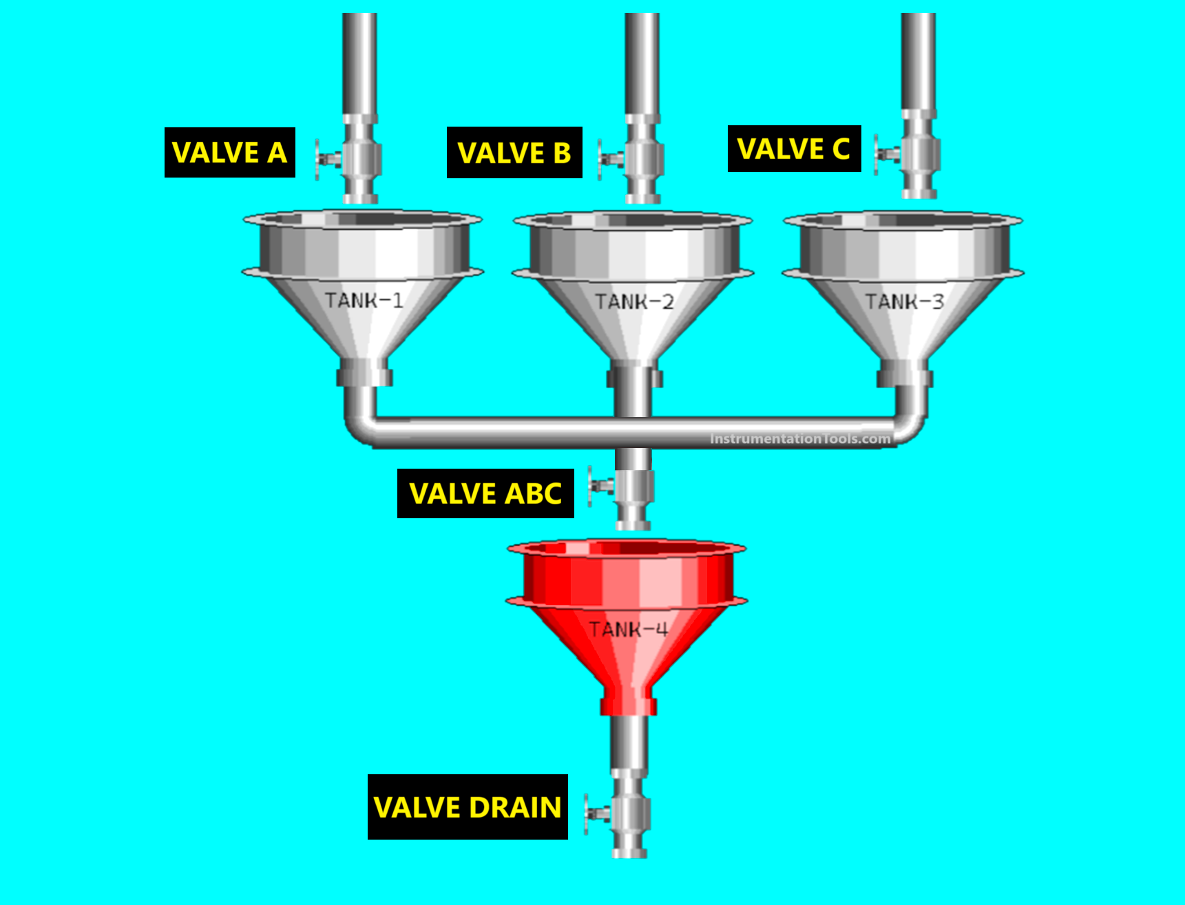
This system can only be started if Tank 4 is empty.

When this system is started, the process of filling liquid raw materials will be carried out in Tanks 1, 2, and 3.

  1. Valve VALVE_A (100.00) will OPEN and fill liquid raw material-A into Tank-1, the filling process will Stop when the weight of the liquid in Tank-1 has reached 10 Kg and Valve VALVE_A (100.00) will CLOSE.
  2. Valve VALVE_B (100.01) will OPEN and fill liquid raw material-B into Tank-2, the filling process will Stop when the weight of the liquid in Tank-2 has reached 15 Kg and Valve VALVE_B (100.01) will CLOSE.
  3. Valve VALVE_C (100.02) will OPEN and fill liquid raw material-C into Tank-3, the filling process will Stop when the weight of the liquid in Tank-3 has reached 20 Kg and Valve VALVE_C (100.02) will CLOSE.

After the raw material A, B, and C filling process is complete, Valve VALVE_OUT_ABC (100.03) will OPEN for 20 seconds to drain all the liquid raw materials into Tank-4.

Next, the Mixing Process will be carried out for 50 seconds, The Mixer Agitator MIXER (100.04) will rotate when the Mixing Process is carried out.

The mixed liquid will be removed from Tank-4 when the Mixing Process is complete. Valve VALVE_DRAIN (100.05) will OPEN until the liquid in Tank-4 is empty.

The system can be started again if Tank-4 is empty.

Batch system programming

Addressing of PLC Project

CommentInput (I)Output (Q)Memory WordMemory BitsTimer
PB_START0.00    
PB_STOP0.01    
VALVE_A 100.00   
VALVE_B 100.01   
VALVE_C 100.02   
VALVE_OUT_ABC 100.03   
MIXER 100.04   
VALVE_DRAIN 100.05   
TIMER1    T0000
TIMER_MIXER    T0001
SYSTEM_ON   W0.00 
IR_CUTOFF_A   W0.01 
IR_CUTOFF_B   W0.02 
IR_CUTOFF_C   W0.03 
IR_CUTOFF_DRAIN   W0.04 
PV_TANK_1  D0  
PV_TANK_2  D1  
PV_TANK_3  D2  
PV_TANK4  D4  

CX-Programmer Programming

RUNG 0 (SYSTEM_ON)

In this Rung, if the value in memory word PV_TANK4 (D3) is equal to zero “0” and the PB_START (0.00) button is pressed, then the memory bit SYSTEM_ON (W0.00) will be in the HIGH state. Because it uses the KEEP(011) instruction, the memory bit SYSTEM_ON (W0.00) will remain in the HIGH state even though the PB_START (0.00) button has been Released.

The memory bit SYSTEM_ON (W0.00) returns to the LOW state if the PB_STOP (0.01) button is Pressed.

4 tank PLC batch process

RUNG 1 (TANK 1 FILLING)

When the NO contact of memory bit SYSTEM_ON (W0.00) in the HIGH state, then Output VALVE_A (100.00) will be OPEN. And when the value in memory word PV_TANK_1 (D0) is equal to 10, then the memory bit IR_CUTOFF_A (W0.01) will be in the HIGH state.

Output VALVE_A (100.00) will become CLOSE due to the Interlock of memory bit IR_CUTOFF_A (W0.01).

CX-Programmer batch mixing example

RUNG 2 (TANK 2 FILLING)

When the NO contact of memory bit SYSTEM_ON (W0.00) is in the HIGH state, the Output VALVE_B (100.01) will be OPEN. And when the value in memory word PV_TANK_2 (D1) is equal to 15, then the memory bit IR_CUTOFF_B (W0.02) will be in the HIGH state.

Output VALVE_B (100.01) will become CLOSE due to the Interlock of memory bit IR_CUTOFF_B (W0.02).

RUNG 3 (TANK 3 FILLING)

When the NO contact of memory bit SYSTEM_ON (W0.00) is in the HIGH state, the Output VALVE_C (100.02) will be OPEN. And when the value in memory word PV_TANK_3 (D2) is equal to 20, the memory bit IR_CUTOFF_C (W0.03) will be in the HIGH state.

Output VALVE_C (100.02) will become CLOSE due to the Interlock of memory bit IR_CUTOFF_C (W0.03).

PLC software for batch mixing

RUNG 4 (TANK 4 FILLING)

When the NO contacts of memory bits IR_CUTOFF_A (W0.01), IR_CUTOFF_B (W0.02), and IR_CUTOFF_C (W0.03) are in the HIGH state, the Output VALVE_OUT_ABC (100.03) will be OPEN and the Timer TIMER1 (T0000) will Start counting up to 20 seconds.

The Output VALVE_OUT_ABC (100.03) will CLOSE if Timer TIMER1 (T0000) has finished counting.

RUNG 5 (MIXING TIME)

In this Rung, when the NO contact of Timer TIMER1 (T0000) in the HIGH state, the MIXER (100.04) Output will be ON and the TIMER_MIXER (T0001) Timer will Start counting up to 50 seconds.

Output MIXER (100.04) will turn OFF when Timer TIMER_MIXER (T0001) has finished counting.

Fluid industry batch mixing PLC

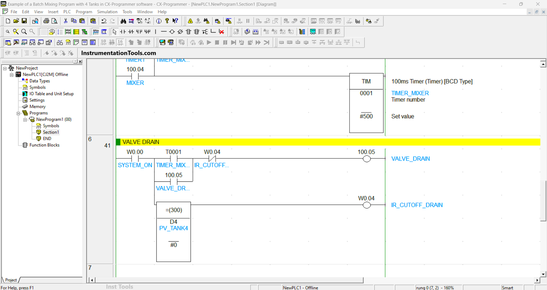
RUNG 6 (VALVE DRAIN)

In this Rung, when the NO contact of memory bit SYSTEM_ON (W0.00) and the TIMER_MIXER (T0001) timer are in the HIGH state, the VALVE_DRAIN (100.05) output will be OPEN.

When the value in memory word PV_TANK4 (D4) is zero “0”, then the memory bit IR_CUTOFF_DRAIN (W0.04) will be in the HIGH state so that the Output VALVE_DRAIN (100.05) returns CLOSE.

Read Next:

  • Simple Conveyor Control PLC Program Example
  • PLC Sequential Control of Three Lights with Reset
  • Structured Text PLC Example for Motor Interlock
  • Allen Bradley PLC to PLC Communication Tutorial
  • PLC Packing Machine Control System Program
Don't Miss Our Updates
Be the first to get exclusive content straight to your email.
We promise not to spam you. You can unsubscribe at any time.
Invalid email address
You've successfully subscribed !
Package System Architecture – Control & Instrumentation
Data Handling Instructions in PLC Programming
PLC Program for Traffic Light Sequence using Functional Blocks
#17 PLC Best Practices – Log PLC Uptime and Trend it on HMI
Playground Swing Logic Exercise Program in PLC
Share This Article
Facebook Whatsapp Whatsapp LinkedIn Copy Link
Share
Leave a Comment

Leave a Reply Cancel reply

Your email address will not be published. Required fields are marked *

Stay Connected

128.3kFollowersLike
69.1kFollowersFollow
208kSubscribersSubscribe
38kFollowersFollow

Categories

Recent Comments

  • Kamli on Top Free PLC Software
  • Guifty Shimica on Top Non-PLC Certification Courses for Automation Professionals
  • Guifty Shimica on Top Non-PLC Certification Courses for Automation Professionals
  • MIHARITSOA Aina Sitraka on Top Non-PLC Certification Courses for Automation Professionals

Related Articles

Single Line Diagram of UPS System

UPS Selection Factors for a Control System

Ladder Diagram Example using Memory Bits and Set Coils

Ladder Diagram Example using Memory Bits and Set Coils

car parking example logic

Up Down Counter Instruction in PLC

Connecting Blocks in Functional Block Diagram

Connecting Blocks in Functional Block Diagram – Studio 5000

Analog Instruments

Explaining Various Types of Analog Instruments

Surface Grinding Process using PLC Program

Surface Grinding Process using PLC Program

Automatic Bottle Filling System using PLC

Automatic Bottle Filling System using PLC

Gate Array Logic using PLC

PLC Program to Simulate Gate Array Logic

More Articles

Unbalanced Bridge Circuit

Bridge Circuit Construction

Applications of Tilting Level Switch

How Tilt Level Switch Works ?

GATE Instrumentation Questions and Answers

GATE Instrumentation Questions and Answers

Single Port Globe Valve

How Sliding Stem Valves Work ?

While Do Statement in Structured Text PLC Program

While Do Statement in Structured Text PLC Program

Demister Pads Problem

Problems with Demister Pads – Root Cause Analysis (RCA)

Common Questions on Oil and Natural Gas Industry

Common Questions on Oil and Natural Gas Industry

Technology is Shaping the Future of Education

How Technology is Shaping the Future of Education?

Follow US
All rights reserved. Reproduction in whole or in part without written permission is prohibited.
Welcome Back!

Sign in to your account

Username or Email Address
Password

Lost your password?