Inst ToolsInst ToolsInst Tools
  • Ask
  • Courses
  • Videos
  • Q & A
    • Interview
      • Instrumentation
      • Electronics
      • Electrical
      • Practical Questions
    • MCQ
      • Instrumentation MCQ
      • Electrical MCQ
      • Electronics MCQ
      • Control Systems MCQ
      • Analog Electronics MCQ
      • Digital Electronics MCQ
      • Power Electronics MCQ
      • Microprocessor MCQ
      • Multiple Choice Questions
  • EE
    • Electronics
      • Electronics Q & A
      • Electronic Basics
      • Electronic Devices & Circuits
      • Electronics Animation
      • Digital Electronics
    • Electrical
      • Electrical Basics
      • Electrical Q & A
      • Power Electronics
      • Electrical Machines
      • Electrical Animation
      • Power Systems
      • Switchgear & Protection
      • Transmission & Distribution
  • Measure
    • Control Valves
    • Calibration
    • Temperature
    • Pressure
    • Flow
    • Level
    • Analyzers
    • Switches
    • Vibration
    • Solenoid Valve
  • Control
    • PLC Tutorials
    • Control Systems
    • Safety Instrumented System (SIS)
    • Communication
    • Fire & Gas System
  • More
    • Design
    • Tools
    • Animation
    • Basics
    • Formulas
    • Standards
    • TextBooks
    • Common
    • Software
    • Excel Tools
    • Erection & Commissioning
    • Process Fundamentals
    • Videos
    • Books
Search
All rights reserved. Reproduction in whole or in part without written permission is prohibited.
Reading: Studio 5000 Tutorial: PLC Programming for Digital Alarms
Share
Notification Show More
Font ResizerAa
Inst ToolsInst Tools
Font ResizerAa
  • Courses
  • PLC Tutorials
  • Control Systems
Search
  • Ask
  • Courses
  • Videos
  • Q & A
    • Interview
    • MCQ
  • EE
    • Electronics
    • Electrical
  • Measure
    • Control Valves
    • Calibration
    • Temperature
    • Pressure
    • Flow
    • Level
    • Analyzers
    • Switches
    • Vibration
    • Solenoid Valve
  • Control
    • PLC Tutorials
    • Control Systems
    • Safety Instrumented System (SIS)
    • Communication
    • Fire & Gas System
  • More
    • Design
    • Tools
    • Animation
    • Basics
    • Formulas
    • Standards
    • TextBooks
    • Common
    • Software
    • Excel Tools
    • Erection & Commissioning
    • Process Fundamentals
    • Videos
    • Books
Follow US
All rights reserved. Reproduction in whole or in part without written permission is prohibited.
Inst Tools > Blog > PLC Tutorials > Studio 5000 Tutorial: PLC Programming for Digital Alarms

Studio 5000 Tutorial: PLC Programming for Digital Alarms

Learn how to develop digital alarms for PLC programming using a functional block diagram in Studio 5000 based on process interlocks.

Last updated: September 24, 2024 5:40 am
Viral Nagda
PLC Tutorials
No Comments
Share
6 Min Read
SHARE

When we use digital instruments in PLC logic, we mostly have to develop alarms for them according to the control philosophy. We use it to either interlock a process or just give a warning message to the user.

Contents
PLC Programming for Digital AlarmsStudio 5000 Tutorial

We have to carefully design the logic, considering the criticality of the process. In this post, we will learn how to develop digital alarms for PLC programming using a functional block diagram in Studio 5000 based on process interlocks.

PLC Programming for Digital Alarms

Let us understand the case scenario first. We have a pressure sensor in the system. We use this sensor to create an interlock for the process, in case it becomes high.

This interlock is required to prevent the pressure from going high and damaging the process. There are two cases in the logic.

In the first case, if pressure remains high for 5 seconds, then the system will trip. The system can be restarted only after pressing the alarm reset button. Before the system trip, if pressure becomes normal at any time, then the timers will reset.

In the second case, if pressure remains high for 5 seconds, then we first give a warning message and alarm to the operator. This warning can be used to operate a safety device in the process of bringing the pressure down. If the pressure is still high for more than 5 seconds, then the system will trip.

The system can be restarted only after pressing the alarm reset button. Before the system trip, if pressure becomes normal at any time, then the timers will reset.

Studio 5000 Tutorial

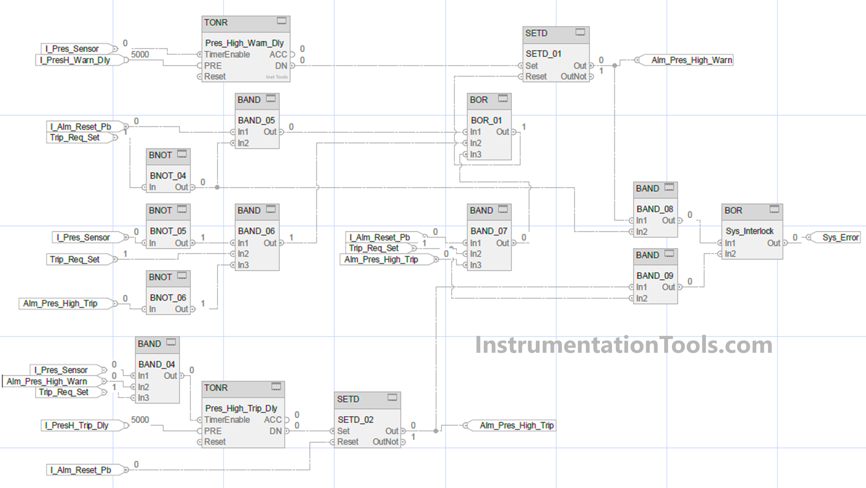
Let us write the logic now. Refer to the below image. We will write using a functional block diagram in Studio 5000 software (Rockwell Automation).

These are the following input variables – pressure sensor, pressure high warning delay set, alarm reset push button, trip logic selection, and pressure high trip delay set.

These are the following output variables – pressure high warning, pressure high trip, and system error.

Studio 5000 Tutorial PLC Programming for Digital Alarms

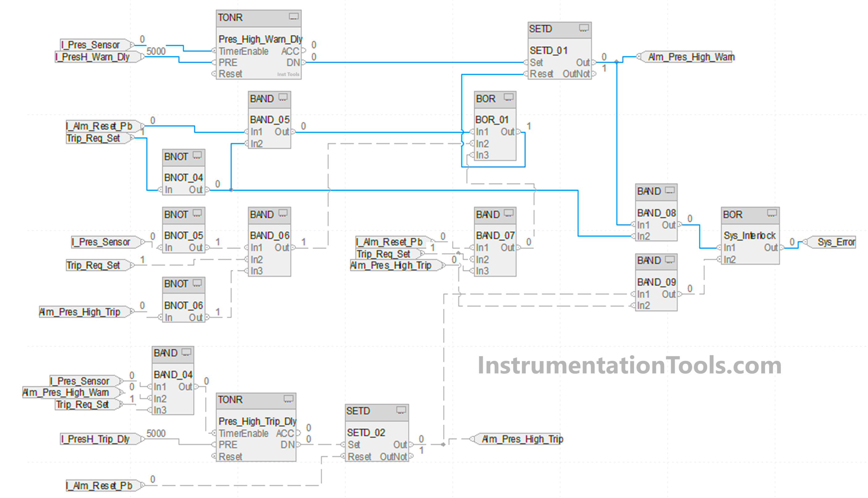
We will see the first case. Refer to the below image. The blue lines indicate the working of the first case. We use a timer for checking high pressure. It starts with the input of a pressure sensor for a set value of 5 seconds. If the timer is running and the pressure input goes low, then the timer is reset. After the timer is done, the bit named alm_pres_high_warn is set.

We used the SETD block here. In this block, there are two inputs – set and reset. If the set bit is high, then the output is set. If the reset bit is high, then the output is reset, on the condition that the set input is not high.

This means that set input is given priority over reset input. For resetting the alarm, we use the AND logic of the reset button and negate trip selection. The sys_error bit is set by using the AND logic of the alarm generated and negating trip selection.

Studio 5000 digital alarms tutorial

We will see the second case. Refer to the below image. The blue lines indicate the working of the second case. We will continue from the first part where the warning bit is set.

Now, the system error will not be generated because we are using trip_req_set now as 1; which will automatically work according to our second scenario.

We use a timer for checking high pressure. It starts with the AND logic of the pressure sensor, alm_pres_high_warn, and trip_req_set for a set value of 5 seconds. After the timer is done, the bit named alm_pres_high_trip is set. We again used the SETD block here.

PLC alarm logic using functional block diagrams

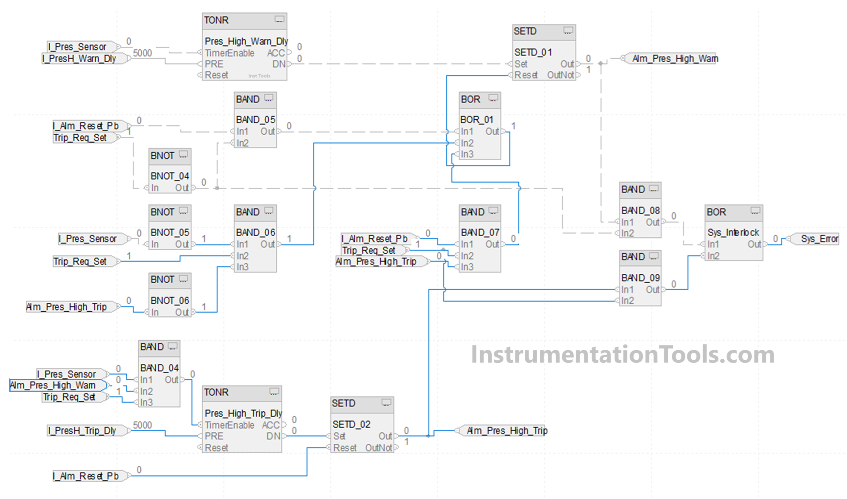
We will see the reset condition of the second case. The first alarm is reset by either this case – negate pressure sensor and trip_req_set selected and negate alm_pres_high_trip (means the alarm is gone if the pressure becomes normal before system trip) or by this case – alarm reset button and trip_req_set selected and alm_pres_high_trip means the alarm is gone if the reset button is pressed after system trip).

The second alarm can be directly reset after pressing the reset button. The sys_error bit is set by using the AND logic of the second alarm generated and trip selection.

In this way, we saw how to write a PLC logic for digital alarms using a functional block diagram.

Read Next:

  • Studio 5000 and FactoryTalk View Studio
  • Analog Input Devices in Studio 5000
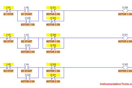
  • Electrical Motor Forward Reverse PLC Logic
  • Product Painting with Omron PLC Program
  • How to Configure an Alarm in InTouch SCADA?
Don't Miss Our Updates
Be the first to get exclusive content straight to your email.
We promise not to spam you. You can unsubscribe at any time.
Invalid email address
You've successfully subscribed !
Components of PLC
Single-acting Pneumatic Cylinder Operation with Limit Switch
Conveyor Sorting System with Color Detection PLC Logic
Sink or Source? Normally Open or Normally Closed?
Elevator Control: PLC Program with 5-Second Floor Stops
Share This Article
Facebook Whatsapp Whatsapp LinkedIn Copy Link
Share
Leave a Comment

Leave a Reply Cancel reply

Your email address will not be published. Required fields are marked *

Stay Connected

128.3kFollowersLike
69.1kFollowersFollow
208kSubscribersSubscribe
38kFollowersFollow

Categories

Recent Comments

  • Kamli on Top Free PLC Software
  • Guifty Shimica on Top Non-PLC Certification Courses for Automation Professionals
  • Guifty Shimica on Top Non-PLC Certification Courses for Automation Professionals
  • MIHARITSOA Aina Sitraka on Top Non-PLC Certification Courses for Automation Professionals

Related Articles

Sequential Timer Control of Lamps

Schneider PLC Example: Control Lamps Sequences

Open PLC Software

Open Source PLC and SCADA Software

PLC Program for Washing Machine

PLC Program for Washing Machine

Marshalling Panel

What is Marshalling Cabinet?

Mixing Process with Valve Control

PLC Mixing Process with Adjustable Timer and Valve Control

Read Temperature in PLC

PLC Program to Read Temperature in PLC

Industrial Automation and Control Systems (IACS)

Industrial Automation and Control Systems (IACS)

PLC Ladder Logic for Lube Oil Pump Motor

PLC Ladder Logic for Lube Oil Pump Motor

More Articles

Single Line Diagram of UPS System

UPS Selection Factors for a Control System

PLC Project Examples for EcoStruxure Machine Expert

PLC Project Examples for EcoStruxure Machine Expert

Van Stone Type Thermowell

Types of Thermowells

Basic Electrical Engineering Interview Questions Answers

Basic Electrical Engineering Interview Questions Answers

Pressure Sensor Temperature Effects

Temperature Compensation for Pressure Measurement

Process Control Automation PLC Quiz

Process Control Automation PLC Quiz

Faceplates

What are Faceplates? How to Create a Faceplate? HMI Visualization

Thermocouple Extension Lead Minimizer Circuit

Thermocouple Wires and Extension Lead Issues

Follow US
All rights reserved. Reproduction in whole or in part without written permission is prohibited.
Welcome Back!

Sign in to your account

Username or Email Address
Password

Lost your password?