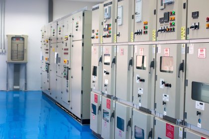
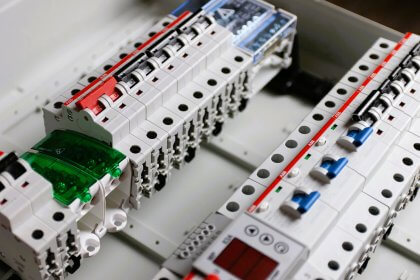
In electrical panels, the components used inside must be able to sustain various types of voltage changes. This is because electricity is random in nature and fluctuations can occur in it, either low or high. If the components used inside are not able to withstand such changes and they break down, then it is a failure of the whole electrical system.
So, there are various types of tests performed to test the validity and efficiency of the system. One such test is called HV or high voltage testing. In this post, we will see why HV testing is done in electrical panels.
What is high voltage testing?
There are many pieces of equipment in an electrical panel which are rated for operating under high voltages and also susceptible to high voltage surges, without any hardware damage. To test such equipment under operational policies for a safe environment in future, a test needs to be done to test their working under high voltages. This is called a high voltage test.
HV test ensures that the device performs for a lifetime in any case of high voltage. This will ensure that the overall electrical system remains safe, the dielectric strength and capacitance of the material are safe for operation, and the breakdown voltage will be withstood by the device.
The normal definition of high voltage is more than 1000V AC and more than 1500V DC. Voltages given in this range to a device define that high voltage testing can be done properly.
If this test is performed in an electrical panel, then after commissioning, the devices like circuit breakers, transformers, contactors, and other high voltage equipment will perform under actual high voltage circumstances during operation; thus ensuring that the device does not break down.
Risk factors and safety in high voltage operation
We know that when we touch a live wire, we get an electric shock. If the voltage is high, then it may even cause death. Serious burns can occur.
Let alone such high voltage; do you know that even a small current like mA (above 30 mA) can cause a small amount of shocks in the human body? Yes, that is true. That is why high voltages must be handled very carefully. During test procedures, the very first step is to first follow the safety guidelines.
It is important to wear safety glasses, gloves, HV suits and tie grounding straps from jackets and pants together. Without these safety gear, it is not advised to perform the tests. Because high voltage shocks can also occur in the air (also called arc flash) and not only by touching, it is advised to stand at a distance before conducting the tests and shutting the system down.
How to perform an HV test?
Before performing the test, there are some points to be noted for carrying out the activities:
- Ensure that the control supply in the panel is off (there is no need to turn off the high voltage power supply flowing in the panel, only the low voltage control supply should be off).
- Perform a Megger test to ensure that any phase is not short-circuited or there is no insulation breakdown (the resistance should be infinite between body to body, body to earth, phase to earth, or neutral to earth. This will ensure that there is no short circuit in the line.)
- Now, to start the HV test, equipment is available in the market called HV tester, which provides a high voltage in it’s two output leads. You need to connect these two leads to the points where the voltage will be checked. The main motive is that after providing high voltage for a certain period of time (typically 1 minute), there should not be any indication of short-circuit (short-circuit can occur either due to any prevailing condition or due to insulation breakdown).
- When you provide high voltage between the two points (phase to earth, phase to neutral or phase to phase), the voltage will flow in the whole connected circuit for the time you have given. During this interval, if everything is fine and there is no short-circuit, the machine will not give any indication. But, if there comes any short-circuit during this voltage application, then the machine will trip immediately and give an indication. This shows that in the corresponding point where you have connected the leads, a short-circuit condition is present in some point. This depicts that the fault area either had some fault prematurely or it’s insulation broke down during testing which caused the leak.
- For example, if you have connected the leads between R-phase and Y-phase, a high voltage will flow in the lines where these two wires are connected (remember that as the control power supply is off, power will not flow in them. For safety purposes, instead of turning off supply, just remove the fuse). One thing to note is that the full voltage is not applied immediately; it is increased gradually up to it’s rated insulation level. Also, when the test is stopped, the voltage is decreased gradually. If the two wires are able to withstand this high voltage for a minute, it means that the conductors (wires, busbar plates or any other equipment where the current is flowing) have good insulation and dielectric strength which does not cause any leakage of electric current outside. Otherwise, it would have resulted in a short circuit and caused the machine to trip.
Remember to not conduct HV tests repeatedly, otherwise the insulation will become weak quickly after a certain point of time. So, perform all the tests in one go with proper planning. Also, ensure that the power supply frequency is present fully during this test (depending on the country where you are performing the test) and the place where the test is carried out is dry and not wet weather or environment.
In this way, we saw the importance of HV testing in electrical panels.
Read Next:
- Difference Between HV and LV Cables
- What are Ground Faults and Earth Faults?
- Transformer Open and Short Circuit Tests
- Control Two Motors in Sequence Circuit
- Compare Core and Shell Transformers