In industrial automation, it is often required that data be shared between two PLCs. This helps for quick information exchange. Also, a system sitting in a remote location will be able to share its data with a central PLC and make itself safe for operation in case of any untoward incident. So, PLC programs have communication libraries and blocks in them for ease.
Allen Bradley PLC to PLC Communication
One of the most used brands is Rockwell Automation and the software generally used in it is Studio 5000. In this post, we will see the concept of PLC to PLC communication in Studio 5000 software of Rockwell Automation.
Produced – Consumed tags
This is one of the most powerful tools of Studio 5000 which makes it outstanding in this feature. As the name implies, a producer is a tag that writes and a consumer is a tag that reads. In this case, there is no need for a communication instruction or block in the program. The tags directly communicate with each other when they are defined as producer and consumer.
Refer to the first image. You have to add the controller from where you want to read data in the Ethernet section.
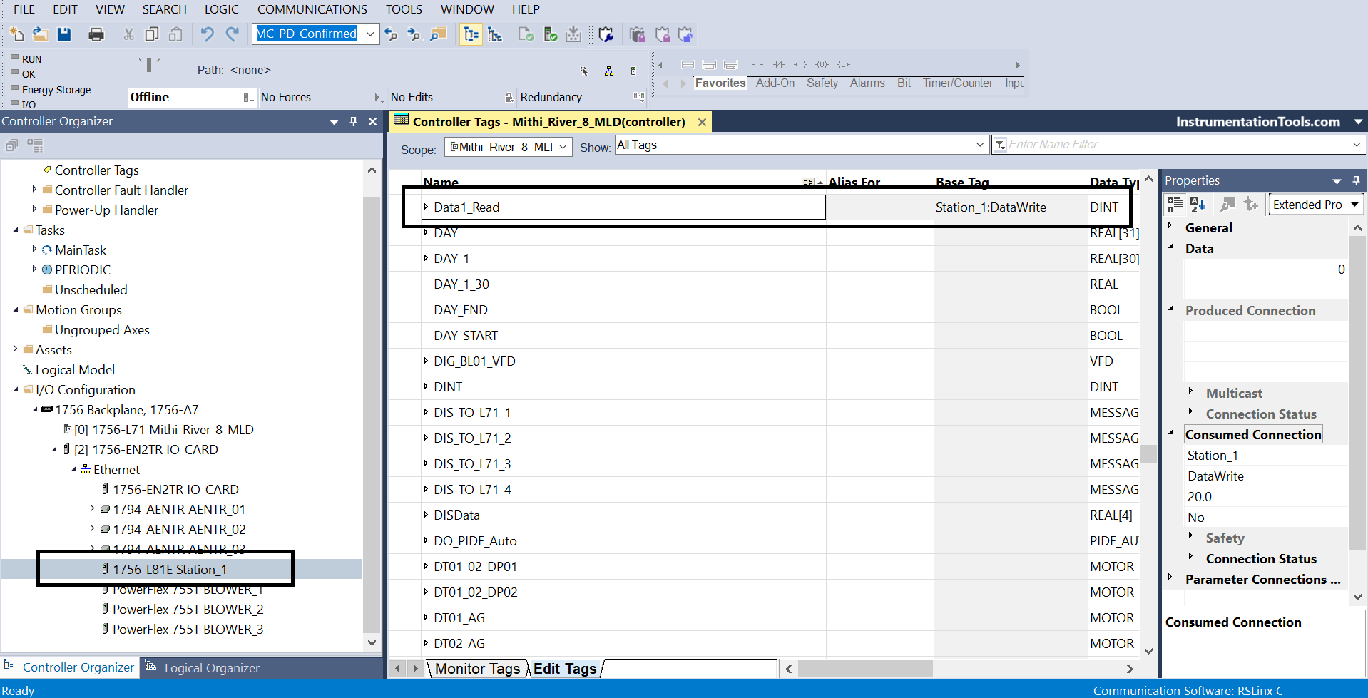
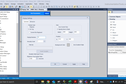
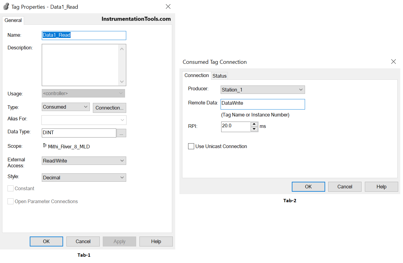
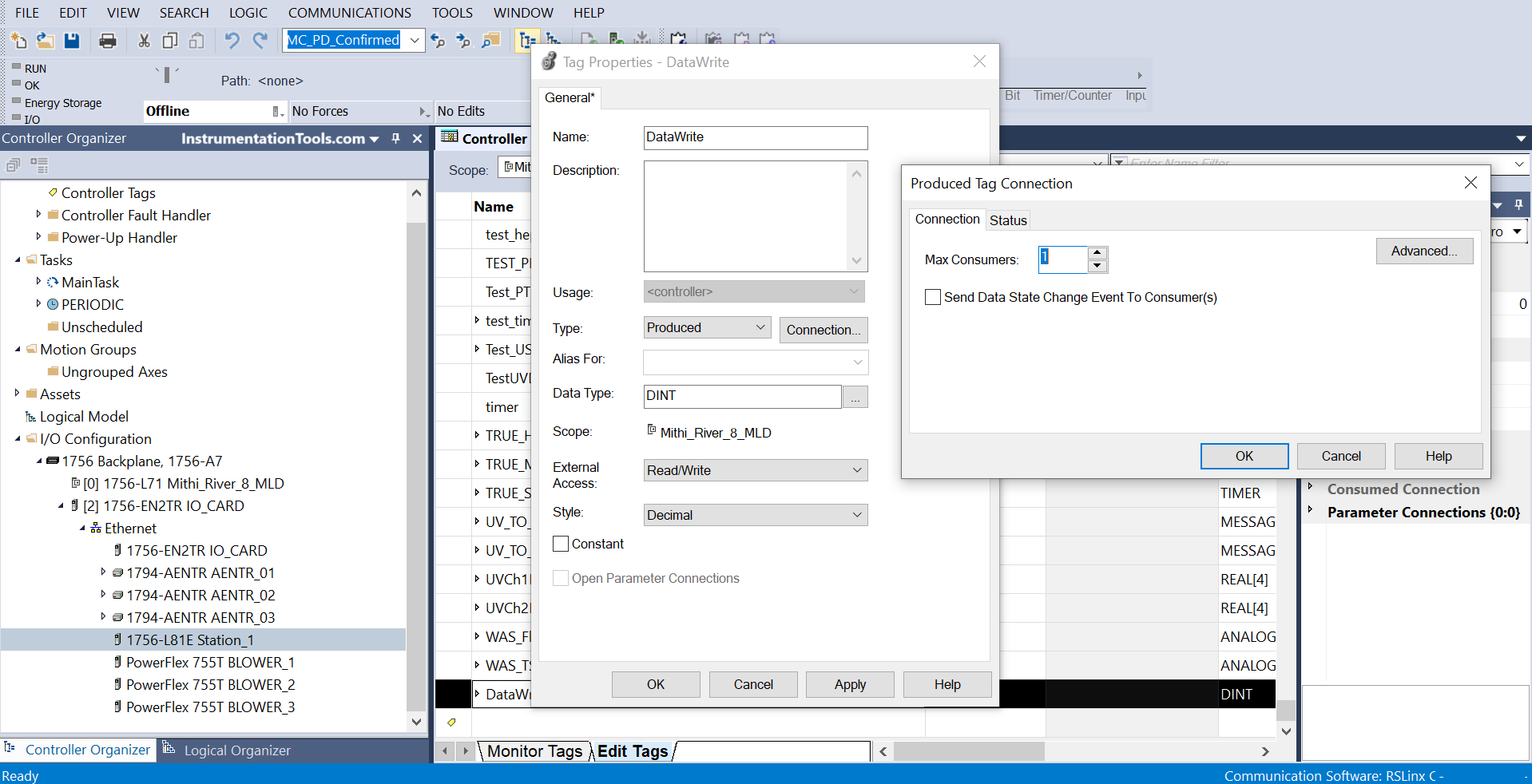
Then, create a tag and edit its properties as shown in the second image.
The Data1_Read will read values from the DataWrite tag in the other PLC.
Now, to create a tag in that other PLC, you must create a producer tag as shown in the third image. Here, you have the option to edit how many PLC’s can consume this tag at a time.
This concept is literally very easy and reduces any need for writing communication blocks or instructions in the program.
Message Instruction
One drawback of the first method is that it communicates only with main CPU PLC’s and not some other remote IO modules or other types of Ethernet devices. So, to communicate with them too or some PLC which is in a remote location and not directly connected on the main PLC backplane, this instruction is used.
Refer to the below image. Here, the instruction has the following three tabs – configuration, communication, and tag.
Let us see the configuration tab first.
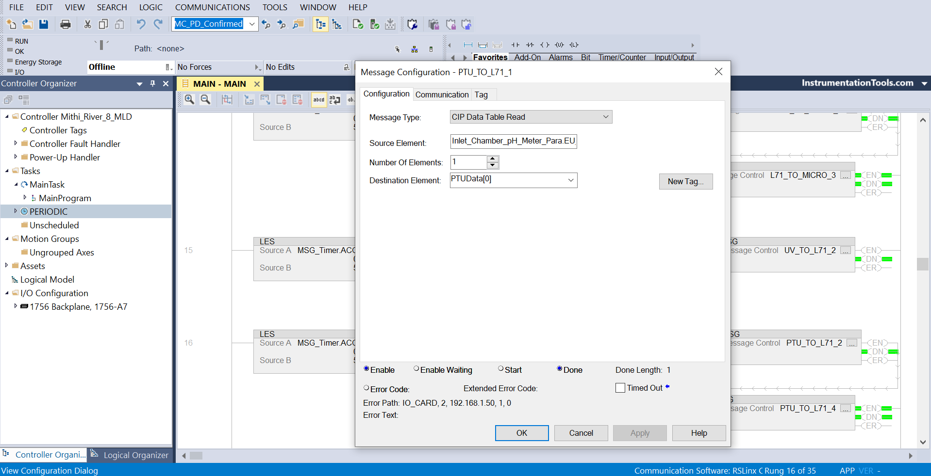
The message type has many variations in it according to the programmer’s requirement, the storage element is the tag of another PLC in case of read and the tag of the same PLC in case of write.
The number of elements shows how many tags you want to read if the source tag is an array, and the destination element is the tag of another PLC in case of write and the tag of the same PLC in case of read. Below this, you get to see the status of the communication.
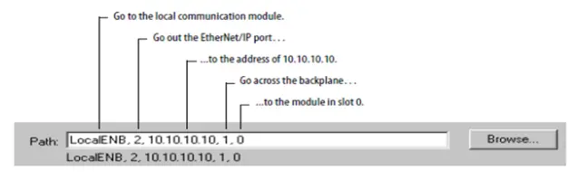
In the second image, you set the communications tab. In the path, refer to the following syntax as shown. It starts from the local PLC port where you are programming and goes on to access the destination PLC where you are communicating.
The third tab – tag, is nothing but the name of the message block instance. So, if you are using three message blocks, then all of them must have different names.
Now, let us come to the part where we have to program this block.
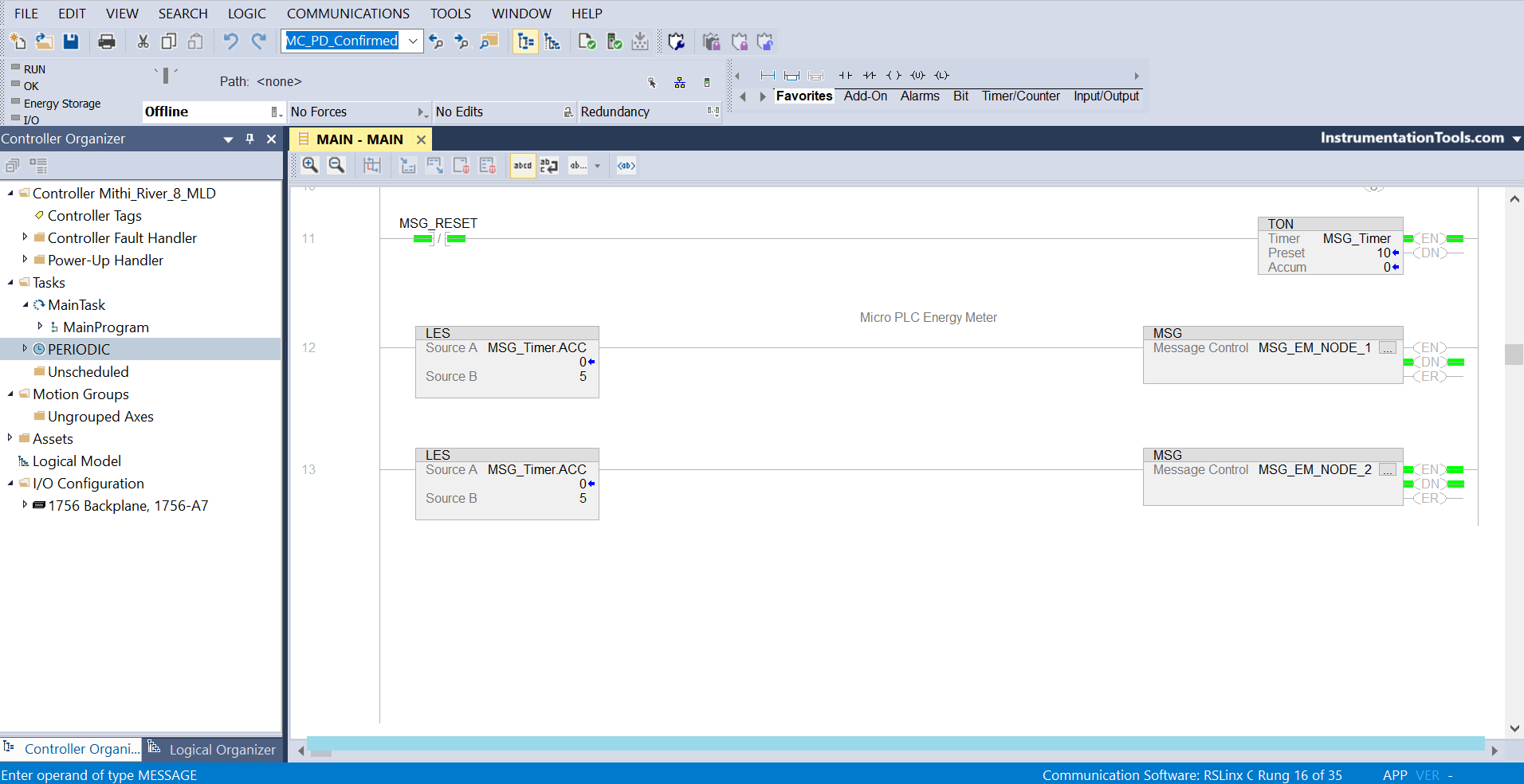
Refer to the below image. You have to execute the blocks in shots and must not be continuously on. Otherwise, the block will not communicate.
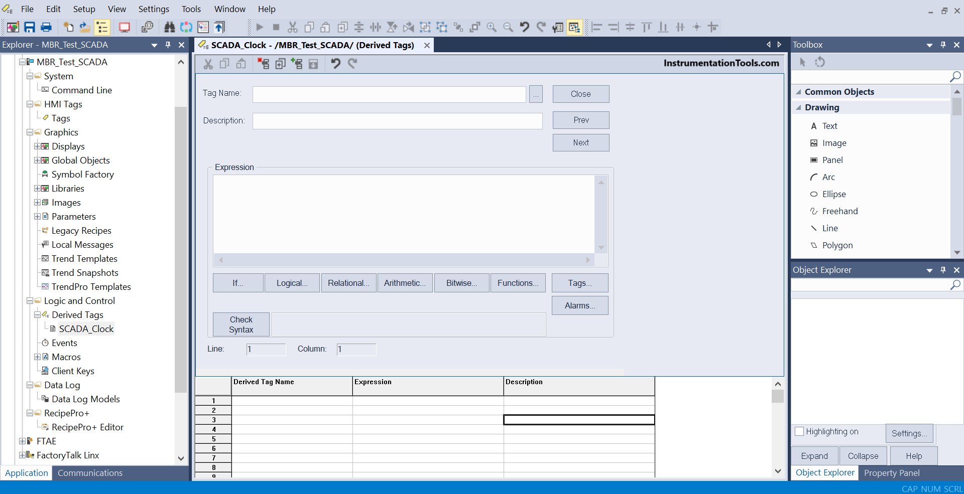
FactoryTalk View Studio Communication Path
This is by far the easiest and strongest one, where you can communicate with any PLC or remote IO module. As you know, FactoryTalk directly reads tags from any IO module or PLC through RSLinx Classic.
So, if you have configured two PLCs in a system and are connected to a network with SCADA, use this option of derived tags as shown below. Write your read tag in the expression and write the tag in the derived tag name.
Call this derived tags section in a frequency. Due to this, the tag from read PLC will be written to write PLC. The major drawback here is that if the SCADA PC fails, then the communication between PLCs will not happen.
In this way, we saw PLC to PLC communication in Allen Bradley – Studio 5000.
Read Next:
- Seven Segment Display PLC STL Programming
- Why different PLC Programming Languages?
- Create Templates in FactoryTalk View Studio
- Configure PlantPAx Library in Factory Talk Studio
- Design Studio 5000 & FactoryTalk View Studio