Generally it is possible to generate a “custom” linear equation in the form of y = mx + b for any linear responding instrument relating input directly to output, a more general approach may be used to relate input to output values by translating all values into (and out of) per unit quantities.
A “per unit” quantity is simply a ratio between a given quantity and its maximum value. A half-full glass of water could thus be described as having a fullness of 0.5 per unit.
-The concept of percent (“per one hundred”) is very similar, the only difference between per unit and percent being the base value of comparison: half-full glass of water has a fullness of 0.5 per unit (i.e. 1/2 of the glass’s full capacity), which is the same thing as 50 percent (i.e. 50 on a scale of 100, with 100 representing complete fullness).
How to do 4-20mA Conversions
Let’s now apply this concept to a realistic 4-20 mA signal application. Suppose you were given a liquid level transmitter with an input measurement range of 15 to 85 inches and an output range of 4 to 20 milliamps, respectively, and you desired to know how many milliamps this transmitter should output at a measured liquid level of 32 inches.
Both the measured level and the milliamp signal may be expressed in terms of per unit ratios, as shown by the following graphs:

So long as we choose to express process variable and analog signal values as a per unit ratios ranging from 0 to 1, we see how m (the slope of the line) is simply equal to the span of the process variable or analog signal range, and b is simply equal to the lower-range value (LRV) of the process variable or analog signal range.
The advantage of thinking in terms of “per unit” is the ability to quickly and easily write linear equations for any given range.
In fact, this is so easy that we don’t even have to use a calculator to compute m in most cases, and we never have to calculate b because the LRV is explicitly given to us.
The instrument’s input equation is y = 70x+15 because the span of the 15 to 85 inch range is 70, and the LRV is 15. The instrument’s output equation is y = 16x+4 because the span of the 4-to-20 milliamp range is 16, and the LRV is 4.
If we manipulate each of the y = mx + b equations to solve for x (per unit of span), we may express the relationship between the input and output of any linear instrument as a pair of fractions with the per unit value serving as the proportional link between input and output:

The question remains, how do we apply these equations to our example problem: calculating the milliamp value corresponding to a liquid level of 32 inches for this instrument?
The answer to this question is that we must perform a two-step calculation: first, convert 32 inches into a per unit ratio, then convert that per unit ratio into a milliamp value.
First, the conversion of inches into a per unit ratio, knowing that 32 is the value of y and we need to solve for x:
32 = 70x + 15
32 − 15 = 70x
x = 0.2429 per unit (i.e. 24.29%)
Next, converting this per unit ratio into a corresponding milliamp value, knowing that y will now be the current signal value using m and b constants appropriate for the 4-20 milliamp range:
y = 16x + 4
y = 16(0.2429) + 4
y = 3.886 + 4
y = 7.886 mA
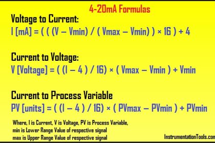
Instead of deriving a single custom y = mx+b equation directly relating input (inches) to output (milliamps) for every instrument we encounter, we may use two simple and generic linear equations to do the calculation in two steps with “per unit” being the intermediate result. Expressed in general form, our linear equation is:
y = mx + b
Value = (Span)(Per unit) + LRV
Value = (URV − LRV)(Per unit) + LRV
Thus, to find the per unit ratio we simply take the value given to us, subtract the LRV of its range, and divide by the span of its range.
To find the corresponding value we take this per unit ratio, multiply by the span of the other range, and then add the LRV of the other range.
Example 1:
Given a pressure transmitter with a measurement range of 150 to 400 PSI and a signal range of 4 to 20 milliamps, calculate the applied pressure corresponding to a signal of 10.6 milliamps.
Solution:
Take 10.6 milliamps and subtract the LRV (4 milliamps), then divide by the span (16 milliamps) to arrive at 41.25% (0.4125 per unit).
Take this number and multiply by the span of the pressure range (400 PSI − 150 PSI, or 250 PSI) and
lastly add the LRV of the pressure range (150 PSI) to arrive at a final answer of 253.125 PSI.
Example 2:
Given a temperature transmitter with a measurement range of −88 degrees to +145 degrees and a signal range of 4 to 20 milliamps, calculate the proper signal output at an applied temperature of +41 degrees.
Solution:
Take 41 degrees and subtract the LRV (-88 degrees) which is the same as adding 88 to 41, then divide by the span (145 degrees − (−88) degrees, or 233 degrees) to arrive at 55.36% (0.5536 per unit).
Take this number and multiply by the span of the current signal range (16 milliamps) and
lastly add the LRV of the current signal range (4 milliamps) to arrive at a final answer of 12.86 milliamps.
Example 3:
Given a pH transmitter with a measurement range of 3 pH to 11 pH and a signal range of 4 to 20 milliamps, calculate the proper signal output at 9.32 pH.
Solution:
Take 9.32 pH and subtract the LRV (3 pH), then divide by the span (11 pH − 3 pH, or 8 pH) to arrive at 79% (0.79 per unit).
Take this number and multiply by the span of the current signal range (16 milliamps) and
lastly add the LRV of the current signal range (4 milliamps) to arrive at a final answer of 16.64 milliamps.
Articles You May Like :
- 4-20mA Transmitters Calculations
- 4 to 20 mA Conversion Formula
- PLC do the Scaling for a Sensor
- 2-wire Transmitters Current Loops
- Basics of 4 to 20 mA analog Signals


i have one query, on regular basis we have faced the problem at our unit.
we can’t do the calibration of Flow meter.
so i need your one standard detail from your if i have 2 inch line on off Ball valve for at inlet of Flowmeter & i have different size flow meter are available to can you please give me maximum flow of flow meter for 1″, 2″, 3″, 4″, …..12″ Max.
so that we can prepare one in house assembly for that & have take idea about Flowmeter.
for Electromagnetic flowmeter & Application VISCOSE
Hi Mr. Reddy, how are you doing? I have a couple favors to ask:
1. Google Chrome keeps kicking me out of your website by stating that there were “too many redirected”.
2. I like to save some articles for references but there were no print or save button to select.
Can you guide me to find the solution for these issues? Thank you for your time.
Hi, Please Try these options :
For Point 1 : Clear Your Google Chrome Full Cache & History, Update the Chrome to latest version.
For Point 2 : Open Any Article > Below the Article > Print Option Available > Click it to save in PDF.
If you face any issue, please mail me the : instrumentationtools@gmail.com
what is the size of flow meter .
Hi I was just wondering if it’s the same if you are measuring a different density Liquid in a level calibration
Hello, can you make calculation for measurement speed (mpm) with encoder
I would use the DockCalc visual calculator SW for such things. You can get a free test version here: https://dockcalc.com/WP/index.php/en/dockcalc-mainpage/downloads/