Inst ToolsInst ToolsInst Tools
  • Courses
  • Automation
    • PLC
    • Control System
    • Safety System
    • Communication
    • Fire & Gas System
  • Instrumentation
    • Design
    • Pressure
    • Temperature
    • Flow
    • Level
    • Vibration
    • Analyzer
    • Control Valve
    • Switch
    • Calibration
    • Erection & Commissioning
  • Interview
    • Instrumentation
    • Electrical
    • Electronics
    • Practical
  • Q&A
    • Instrumentation
    • Control System
    • Electrical
    • Electronics
    • Analog Electronics
    • Digital Electronics
    • Power Electronics
    • Microprocessor
  • Request
Search
  • Books
  • Software
  • Projects
  • Process
  • Tools
  • Basics
  • Formula
  • Power Plant
  • Root Cause Analysis
  • Electrical Basics
  • Animation
  • Standards
  • 4-20 mA Course
  • Siemens PLC Course
Reading: PLC Program for Controlling a Water Pump with 3 Power Sources
Share
Notification Show More
Font ResizerAa
Inst ToolsInst Tools
Font ResizerAa
  • Courses
  • Design
  • PLC
  • Interview
  • Control System
Search
  • Courses
  • Automation
    • PLC
    • Control System
    • Safety System
    • Communication
    • Fire & Gas System
  • Instrumentation
    • Design
    • Pressure
    • Temperature
    • Flow
    • Level
    • Vibration
    • Analyzer
    • Control Valve
    • Switch
    • Calibration
    • Erection & Commissioning
  • Interview
    • Instrumentation
    • Electrical
    • Electronics
    • Practical
  • Q&A
    • Instrumentation
    • Control System
    • Electrical
    • Electronics
    • Analog Electronics
    • Digital Electronics
    • Power Electronics
    • Microprocessor
  • Request
Follow US
All rights reserved. Reproduction in whole or in part without written permission is prohibited.
Inst Tools > Blog > PLC Tutorials > PLC Program for Controlling a Water Pump with 3 Power Sources

PLC Program for Controlling a Water Pump with 3 Power Sources

Example of a PLC Program Controlling a Water Pump with 3 different power sources using Interlock function in CX-Programmer and CX-Designer.

Last updated: July 1, 2024 4:05 pm
Editorial Staff
PLC Tutorials
No Comments
Share
7 Min Read
SHARE

Example of a PLC Program Controlling a Water Pump with 3 different power sources using Interlock function in CX-Programmer and CX-Designer.

Contents
Controlling a Water Pump with 3 Power SourcesI/O ListPLC Program for Controlling a Water PumpSimulation of the PLC Program

Controlling a Water Pump with 3 Power Sources

This article discusses the PLC application of “Latching” and “Interlock” concepts which can be used as a learning medium for students or beginner PLC programmers.

How The PLC Program Works?

The PLC program uses 4 buttons, the START_SYSTEM (0.00) button is used to Turn ON the system, STOP_SYSTEM (0.01) button is used to Turn OFF the system.

The START_SOURCE1 (0.02) button is used to Turn ON the Water Pump using Source 1, START_SOURCE2 (0.03) button is used to Turn ON the Water Pump using Source 2, START_SOURCE3 (0.04) button is used to Turn ON the Water Pump using Source 3.

PLC Program for Controlling a Water Pump with 3 Power Sources

The system will Run when START_SYSTEM (0.00) button is Pressed and results in the memory bit SYSTEM_ON (W0.03) being ON. Because it uses Latching, the memory bit SYSTEM_ON (W0.03) remains ON even though the START_SYSTEM (0.00) button has been released. The memory bit SYSTEM_ON (W0.03) will be OFF if STOP_SYSTEM (0.01) button is Pressed.

This system uses the concept of “Latching” and “Interlock”, so that the memory bits SOURCE1 (W0.00), SOURCE2 (W0.01), and SOURCE3 (W0.02) cannot be ON at the same time, they can only be ON alternately.  When one of the memory bits SOURCE1 (W0.00), SOURCE2 (W0.01), and SOURCE3 (W0.02) is Active then the WATER_PUMP (100.00) Output becomes ON.

I/O List

Addressing Input, Output, TIM, Bit Memory, and Word Memory details are as follows.

CommentInput (I)Output(Q)Memory Bits
START_SYSTEM0.00  
STOP_SYSTEM0.01  
START_SOURCE10.02  
START_SOURCE20.03  
START_SOURCE30.04  
WATER_PUMP 100.00 
SOURCE1  W0.00
SOURCE2  W0.01
SOURCE3  W0.02
SYSTEM_ON  W0.03

PLC Program for Controlling a Water Pump

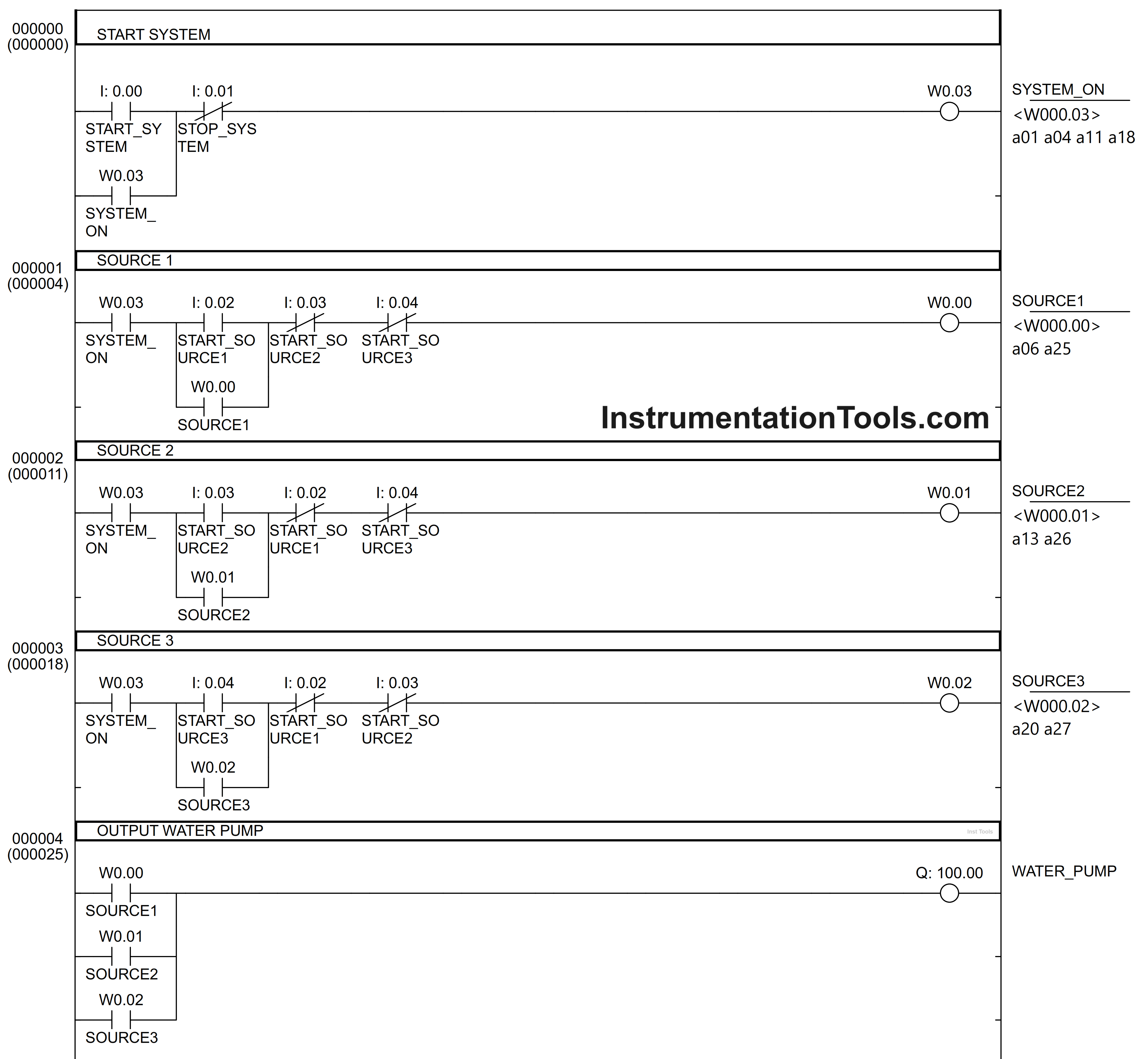
RUNG 0 (START SYSTEM)

In this Rung, when START_SYSTEM (0.00) button is pressed, the memory bit SYSTEM_ON (W0.03) changes to the ON state. Because it uses latching, the memory bit SYSTEM_ON (W0.03) remains ON even though the START_SYSTEM (0.00) button has been Released.

The memory bit SYSTEM_ON (W0.03) will be OFF if the STOP_SYSTEM (0.01) button is Pressed.
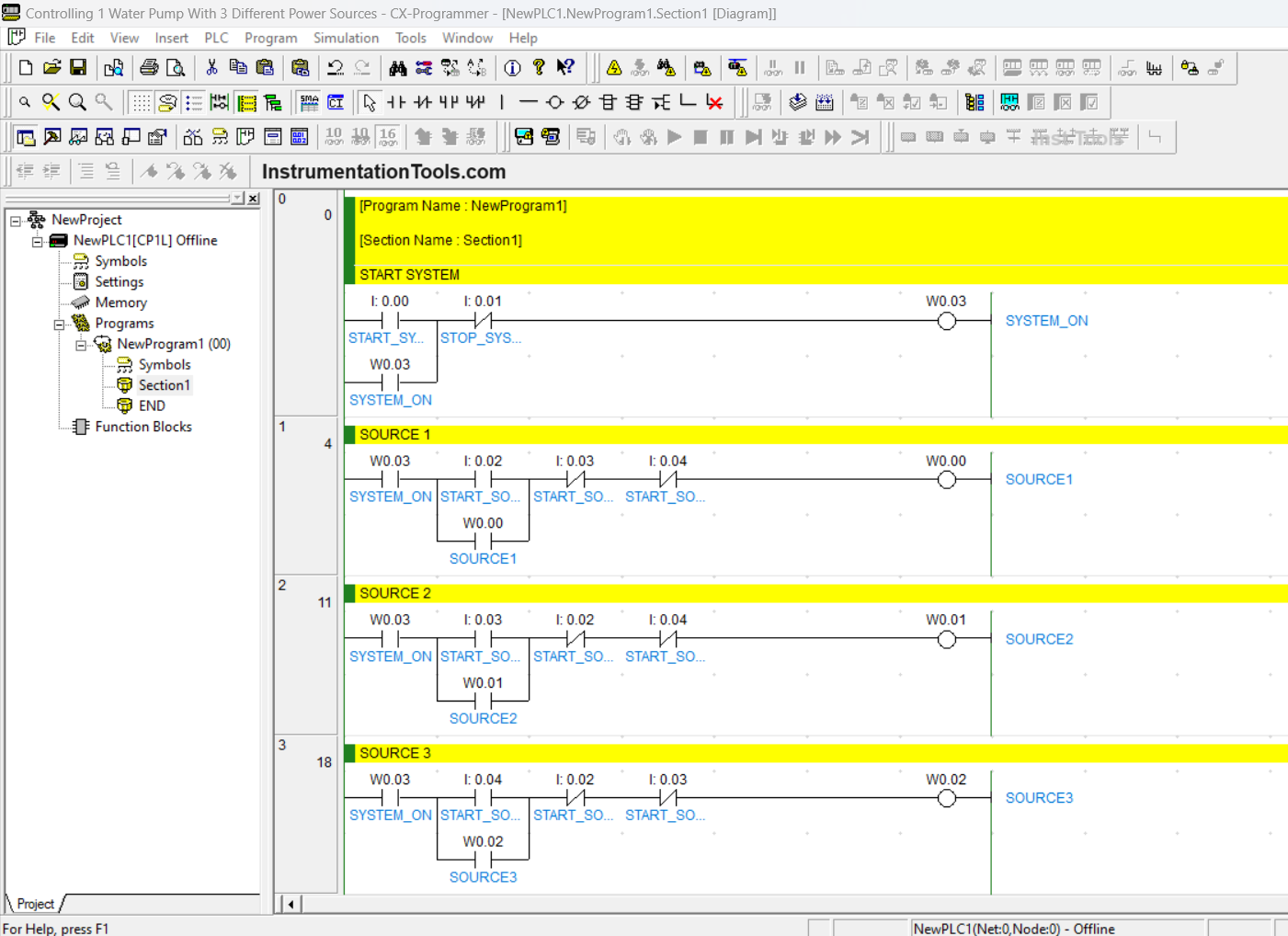
Control of water pump using plc

RUNG 1 (SOURCE 1)

When Normally Open contact of the memory bit SYSTEM_ON (W0.03) is in the HIGH state and START_SOURCE1 (0.02) button is pressed, then the memory bit SOURCE1 (W0.00) changes to the ON state.

Because it uses latching, the memory bit SOURCE1 (W0.00) remains ON even though the START_SOURCE1 (0.02) button has been Released. The memory bit SOURCE1 (W0.00) will be OFF when the Normally Close contact of START_SOURCE2 (0.03) button or START_SOURCE3 (0.04) button is Pressed.

RUNG 2 (SOURCE 2)

When Normally Open contact of the memory bit SYSTEM_ON (W0.03) is in the HIGH state and START_SOURCE2 (0.03) button is pressed, then the memory bit SOURCE2 (W0.01) changes to the ON state.

Because it uses latching, the memory bit SOURCE2 (W0.01) remains ON even though the START_SOURCE2 (0.03) button has been Released. The memory bit SOURCE2 (W0.01) will be OFF when the Normally Close contact of START_SOURCE1 (0.02) button or START_SOURCE3 (0.04) button is Pressed.
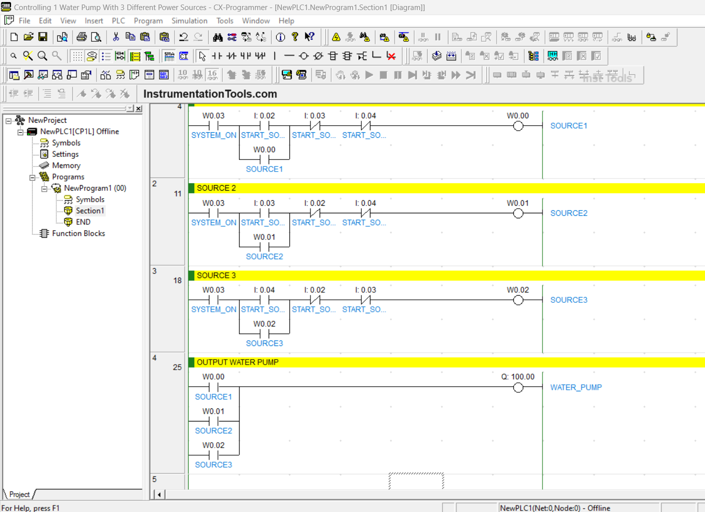
Water Pumping System with PLC

RUNG 3 (SOURCE 3)

When Normally Open contact of the memory bit SYSTEM_ON (W0.03) is in the HIGH state and the START_SOURCE3 (0.04) button is pressed, then the memory bit SOURCE3 (W0.02) changes to the ON state.

Because it uses latching, the memory bit SOURCE3 (W0.02) remains ON even though the START_SOURCE3 (0.04) button has been Released. The memory bit SOURCE3 (W0.02) will be OFF when the Normally Close contact of START_SOURCE1 (0.02) button or START_SOURCE2 (0.03) button is Pressed.

RUNG 3 (WATER PUMP OUTPUT)

In this Rung, when one of the Normally Open contacts of the memory bits SOURCE1 (W0.00), SOURCE2 (W0.01), and SOURCE3 (W0.02) in the HIGH state then the Output WATER_PUMP(100.00) becomes ON.

Simulation of the PLC Program

HMI for Water Pump

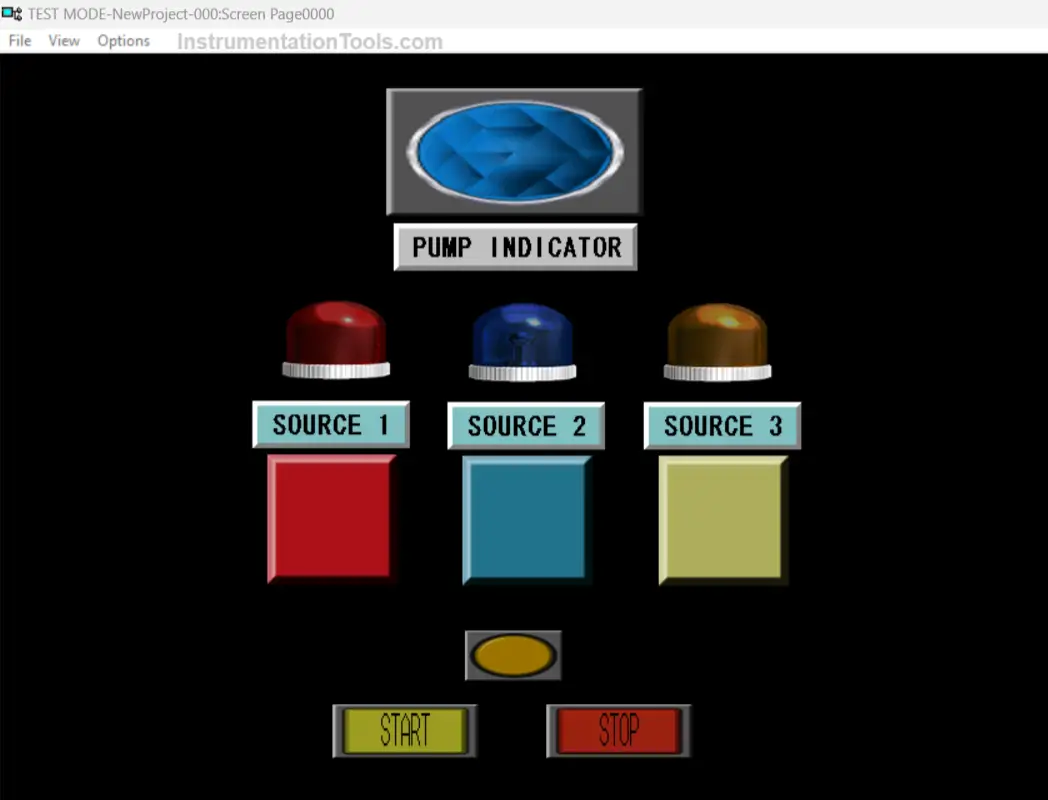
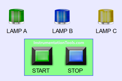
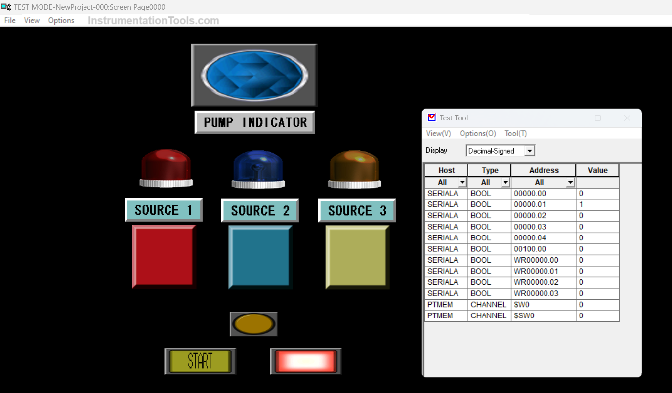
The above image is the HMI (Human Machine Interface) design of the “PLC Program Controlling 1 Water Pump With 3 Different Power Sources using the Interlock Function”.

Water Pump Control with Three Power Sources

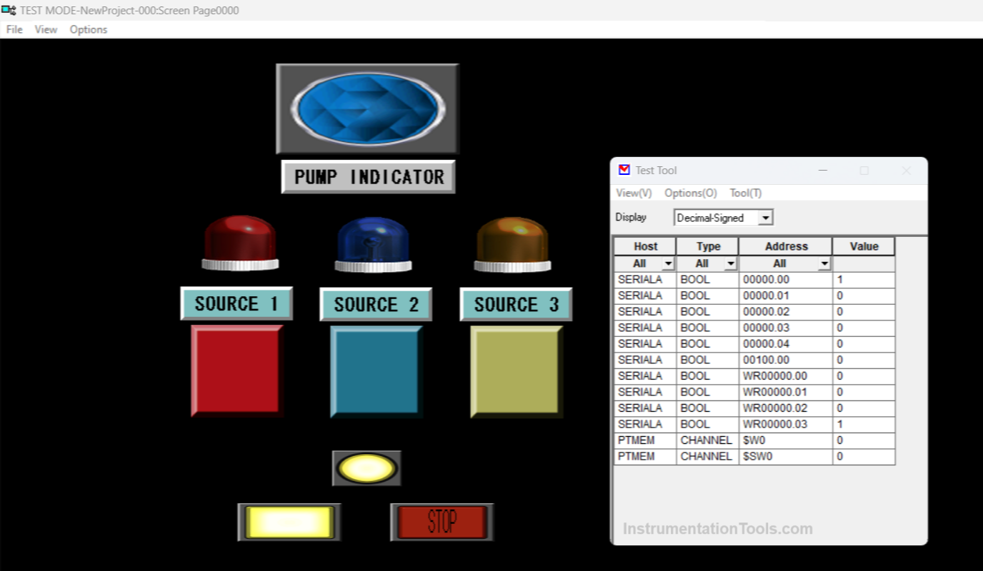
The image above shows, that when START_SYSTEM (0.00) button is pressed, then the SYSTEM_ON (W0.03) indicator light turns on.

PLC indicator light turns on

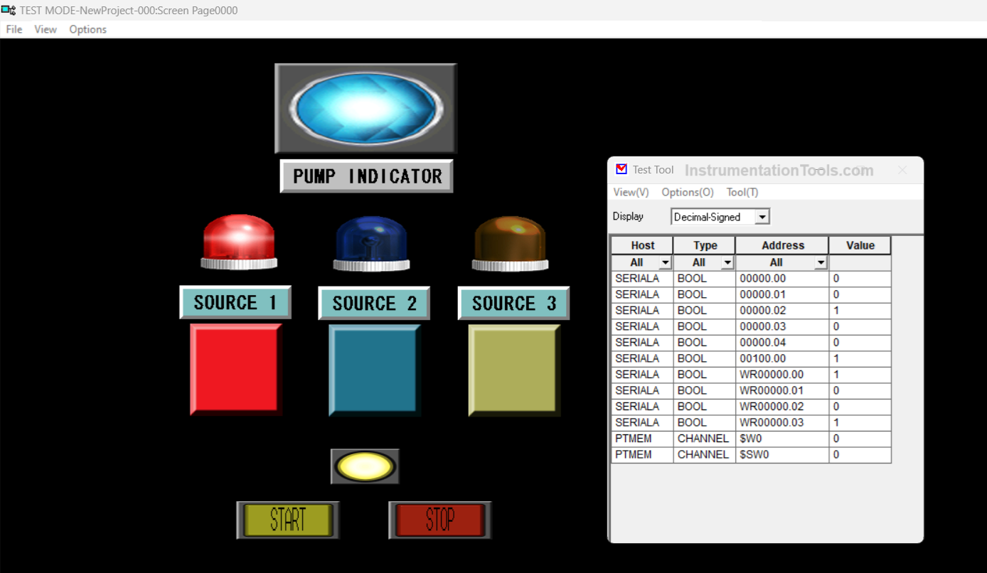
It can be seen in the picture above when the START_SOURCE1 (0.02) button is pressed, then the SOURCE1 (W0.00) and WATER_PUMP (100.00) indicator lights Turn ON.

PLC SCADA Water Pump

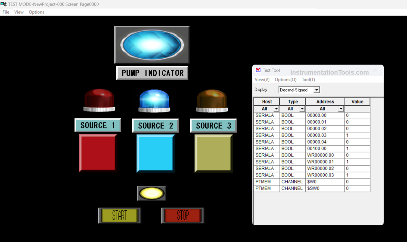
It can be seen in the picture above when the START_SOURCE2 (0.03) button is pressed, then the SOURCE2 (W0.01) and WATER_PUMP (100.00) indicator lights are turned on.

PLC HMI Pump

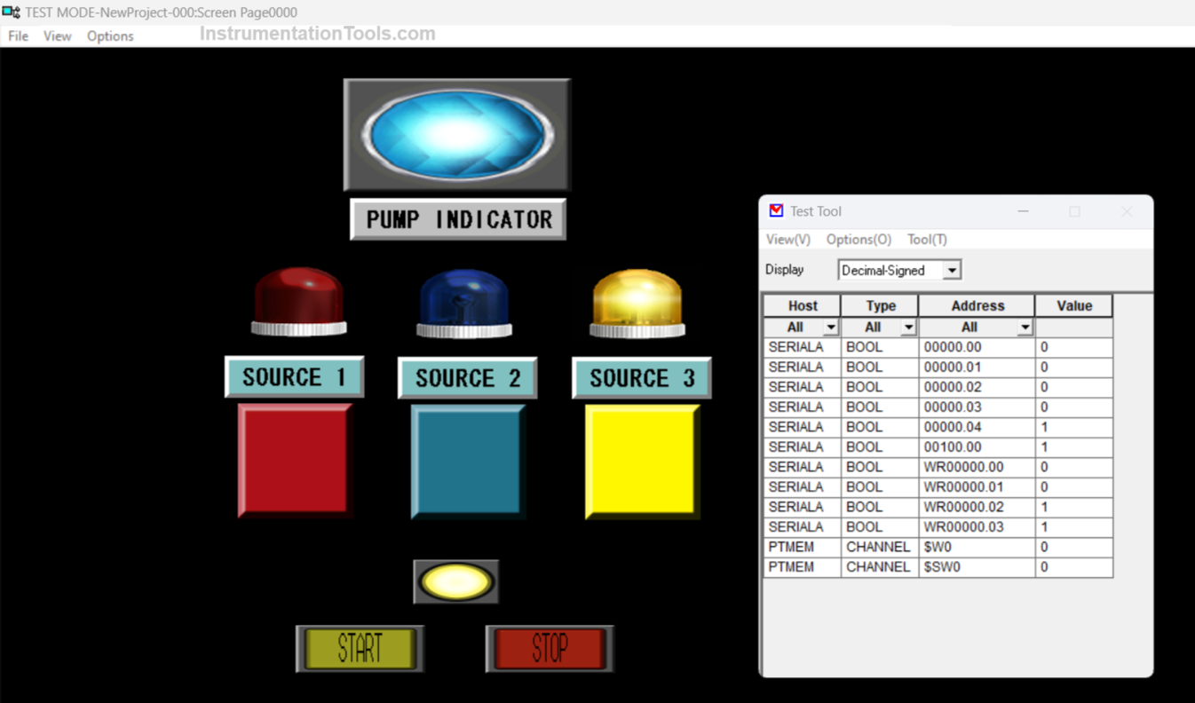
It can be seen in the picture above when the START_SOURCE3 (0.04) button is pressed, then the SOURCE3 (W0.02) and WATER_PUMP (100.00) indicator lights are turned ON.

PLC Pump Status Indicator

The image above shows, when the STOP_SYTEM (0.01) button is pressed and the system turns off.

If you liked this article, please subscribe to our YouTube Channel for PLC and SCADA video tutorials.

You can also follow us on Facebook and Twitter to receive daily updates.

Read Next:

  • PLC Programming for Level Control of Two Tanks
  • Controlling the PLC Output using Push Buttons
  • Light ON OFF Control using PLC Programming
  • PLC Sequence of Conveyors with Interlock Function
  • Increment & Decrement Instructions in OMRON PLC
Don't Miss Our Updates
Be the first to get exclusive content straight to your email.
We promise not to spam you. You can unsubscribe at any time.
Invalid email address
You've successfully subscribed !

Continue Reading

80+ PLC MCQ Questions
1 to 8 Demultiplexer PLC ladder diagram
PLC Batch System for 4 Tanks Mixing using CX-Programmer
Memory Structure of Siemens PLC
PLC Programming Examples on Industrial Automation
Introduction to PLC Ladder Diagrams
Share This Article
Facebook Whatsapp Whatsapp LinkedIn Copy Link
Share
Leave a Comment

Leave a Reply Cancel reply

Your email address will not be published. Required fields are marked *

Stay Connected

128.3kFollowersLike
69.1kFollowersFollow
210kSubscribersSubscribe
38kFollowersFollow

Categories

Explore More

Drive Multiple Speeds with Different Reference using PLC
How does SMPS Works? – Switched Mode Power Supply
AI, AO, DI, DO Questions (PLC I/O Types)
What Factors Affect the Choice of PLC Programming Software?
Actuator Sensor Interface (ASi) Protocol in PLC
Concept of Latching in PLC
Jump Instruction in Siemens Tia Portal
PLC Sequence Programming Ladder Logic

Keep Learning

PLC Multiple Choice Questions

PLC Multiple Choice Questions

Difference between Compact PLC and Modular PLC

Difference between Compact PLC and Modular PLC

Multi Way Switches using PLC

Making Multi Way Switches using PLC

How to Safely Design Automation System for Hazardous Environments?

Automation System for Hazardous Environments

How to Filter Digital and Analog Inputs in a PLC

#7 PLC Best Practices – Validate and Alert for Paired Inputs/Outputs

PLC Example to Control LEDs Via Switches

PLC Example to Control LEDs Via Switches

Siemens Industrial Laptop (Simatic Field PG)

Connect to the Siemens S7 PLC

S7-1200 Hardware Configuration

S7-1200 Hardware Configuration – Siemens PLC Tutorials

Learn More

Typical Switchyard Layout

Electrical Substation – Busbar Arrangements and Layouts

Gang Switch Principle

Reading Electrical Schematics

Power Electronics Objective Questions

GTO Objective Questions and Answers

Wave Trap in Power Line carrier Communication

What is a Wave Trap? – Power Line Carrier Communication

Measure Frequency using Multimeter

How to measure frequency using Multimeter

Chromatography Questions & Answers

Column Efficiency and Column Resolution Questions and Answers

Why Restriction Orifice is some distance from Blowdown valve

Why Restriction Orifice is some distance from Blowdown valve ?

Gas Valve Sizing

Gas Valve Sizing

Menu

  • About
  • Privacy Policy
  • Copyright

Quick Links

  • Learn PLC
  • Helping Hand
  • Part Time Job

YouTube Subscribe

Follow US
All rights reserved. Reproduction in whole or in part without written permission is prohibited.
Welcome Back!

Sign in to your account

Username or Email Address
Password

Lost your password?