Design PLC ladder logic using one switch to program the machine tool and coolant system application.
Note: This PLC exercise can be used to learn the ladder logic programming.
Machine Tool and Coolant Control
Problem Statement:
Design a PLC ladder logic for the following application.
We are using one toggle switch to control the Machine Tool and Coolant.
The Coolant should activate when the Machine Tool starts and continue for 5 seconds after the tool stops. The Machine tool will operate for 40 seconds with a break of 10 seconds.
PLC Ladder Logic Design
Instrumentation Tools YouTube channel offers free tutorials and courses on developing ladder logics with practice problems.
This programming video explains the PLC problem statement and its solution.
Inputs and Outputs
Digital Inputs:
Start Button: I0.0
Digital Outputs:
Machine Tool: Q0.0
Coolant: Q0.1
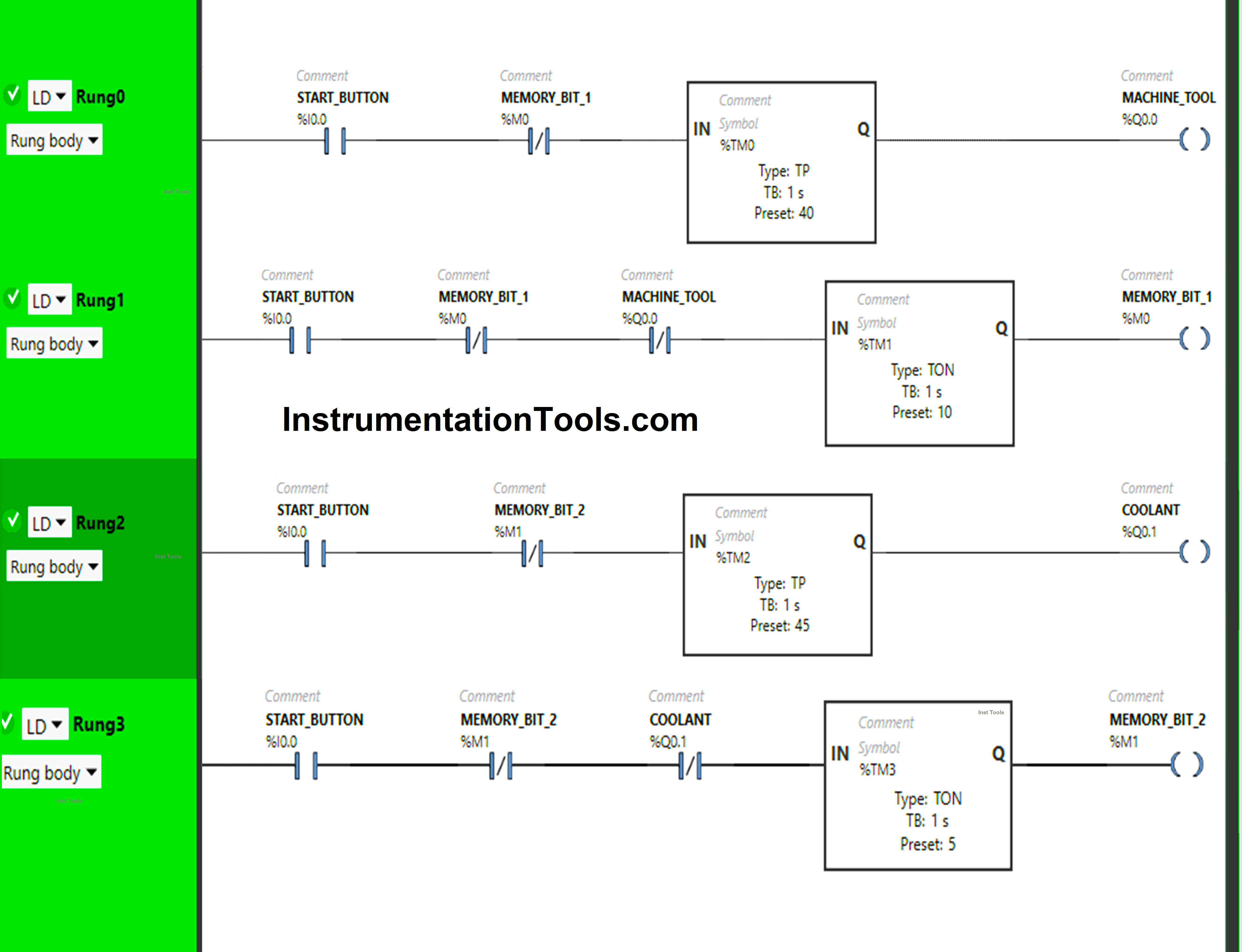
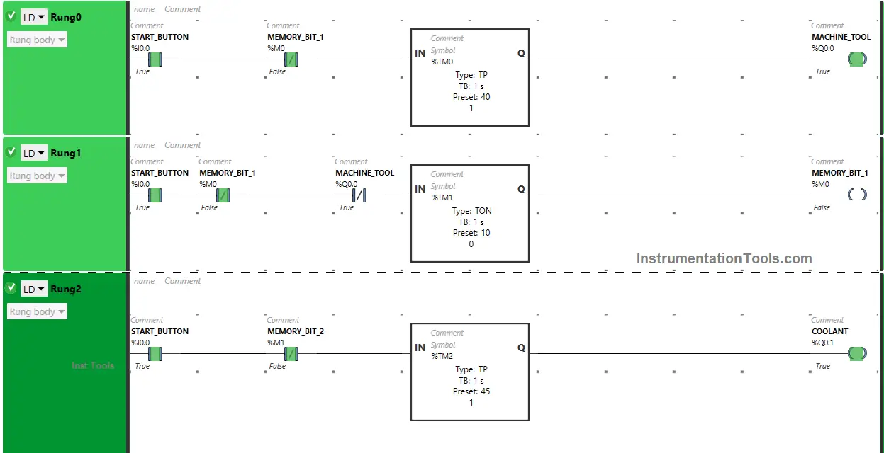
PLC Program
Explanation
We have used Normally Open Contact for the Start Button (I0.0).
In Rung 0:
- Normally Open Contact is used for the Start Button (I0.0) to Turn ON the output Machine Tool (Q0.0).
- Normally Closed Contact is used for Memory Bit 1 (M0) to turn OFF the output Machine Tool (Q0.0).
- Timer Function Block type TP is used to Turn ON the output Machine Tool (Q0.0) for a limited time.
In Rung 1:
- Normally Open Contact is used for the Start Button (I0.0) to Turn ON the Memory Bit 1 (M0).
- Normally Closed Contacts are used for Memory Bit 1 (M0) and Machine Tool (Q0.0) to turn ON Memory Bit 1 (M0).
- Timer Function Block type TON is used to delay the turning ON time of Memory Bit 1 (M0) for some time.
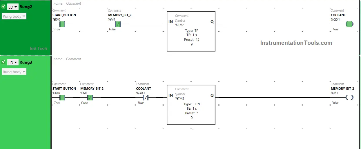
In Rung 2:
- Normally Open Contact is used for the Start Button (I0.0) to Turn ON the output Coolant (Q0.1).
- Normally Closed Contact is used for Memory Bit 2 (M1) to turn OFF the output Coolant (Q0.0).
- Timer Function Block type TP is used to Turn ON the output Coolant (Q0.0) for a limited time.
In Rung 3:
- Normally Open Contact is used for the Start Button (I0.0) to Turn ON the Memory Bit 2 (M1).
- Normally Closed Contacts are used for Memory Bit 2 (M1) and Coolant (Q0.1) to turn ON Memory Bit 2 (M1).
- Timer Function Block type TON is used to delay the turning ON time of Memory Bit 2 (M1) for some time.
Simulation Results: When the Start Button is turned ON
When the Start Button (I0.0) is turned ON, the output Machine Tool (Q0.0) will turn ON in Rung0 and the output Coolant (Q0.1) will turn ON in Rung2 as Normally Open Contact used for Start Button (I0.0) will pass the signal to the outputs.
In False State, Memory Bit 1 (M0) in Rung0 and Memory Bit 2 (M1) in Rung2 also pass the signal to turn ON the outputs, and the outputs Machine Tool (Q0.0) and Coolant (Q0.1) will turn ON but only for limited time as Timer Function Block type TP is used to turn ON the outputs Machine Tool (Q0.0) and Coolant (Q0.1) for limited time.
For Machine Tool, the time is set to 40 seconds. After 40 seconds, the output Machine Tool (Q0.0) will turn OFF and For Coolant, the time is set to 45 seconds. After 45 seconds, the output Coolant (Q0.1) will turn OFF ( Coolant will be ON 5 seconds more than the Machine Tool).
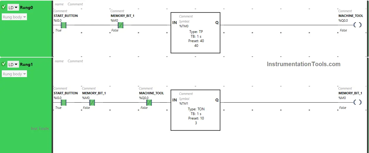
When the Start Button (I0.0) is ON and the output Machine Tool (Q0.0) turns OFF in Rung0, Normally Closed Contact used for the Machine tool (Q0.0) in Rung1 will be in a false state and allows the signal to pass through it to turn ON Memory Bit 1 (M0) in Rung1.
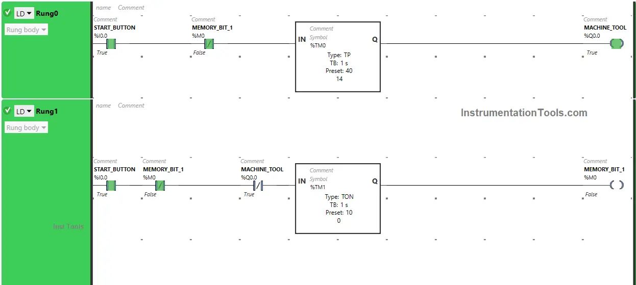
In a false state, Normally Closed Contact used for Memory Bit 1 (M0) in Rung1 will also pass the signal to turn ON Memory Bit 1 (M0), and Memory Bit 1 (M0) will turn ON but after 10 seconds as Timer Function Block type TON is used to delay the turning ON time of Memory Bit 1 (M0).
The time is set to 10 seconds. After 10 seconds, Memory Bit 1 (M0) will turn ON but it will turn OFF within no time because in Rung0, Normally Closed Contact is used for Memory Bit 1 (M0).
In Rung0, Normally Closed Contact used for Memory Bit 1 (M0) will also turn ON and OFF within no time and the output Machine Tool (Q0.0) will turn ON again.
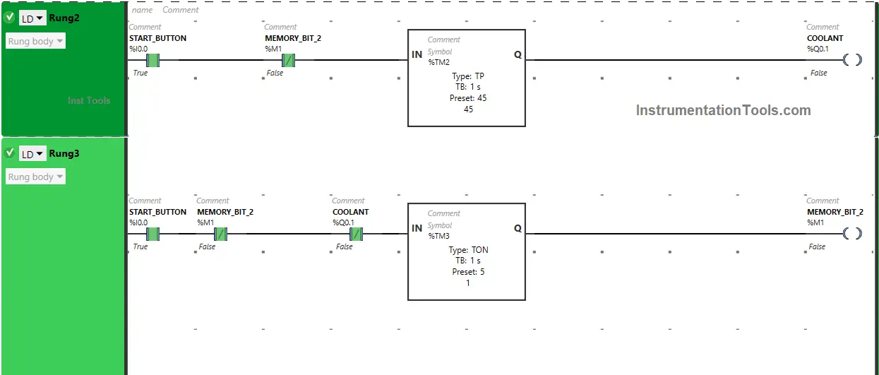
When the Start Button (I0.0) is ON and the output Coolant (Q0.1) turns OFF in Rung2, Normally Closed Contact used for Coolant (Q0.1) in Rung3 will be in a false state and allows the signal to pass through it to turn ON Memory Bit 2 (M1) in Rung3.
In a false state, Normally Closed Contact used for Memory Bit 2 (M1) in Rung3 will also pass the signal to turn ON Memory Bit 2 (M1), and Memory Bit 2 (M1) will turn ON but after 5 seconds as Timer Function Block type TON is used to delay the turning ON time of Memory Bit 2 (M1).
The time is set to 5 seconds. After 5 seconds, Memory Bit 2 (M1) will turn ON but it will turn OFF within no time because in Rung2, Normally Closed Contact is used for Memory Bit 2 (M1).
In Rung2, Normally Closed Contact used for Memory Bit 2 (M1) will also turn ON and OFF within no time and the output coolant (Q0.1) will turn ON again. Then, the whole process runs in a loop.
If you liked this article, please subscribe to our YouTube Channel for PLC and SCADA video tutorials.
You can also follow us on Facebook and Twitter to receive daily updates.
Read Next:
- Alarm Indication in Process Control Ladder Logic
- Automatic Car Washing using PLC Programming
- Light Tower Industrial Automation Programming
- Modbus Communication Questions and Answers
- Three Motors control PLC Programming Logic