Inst ToolsInst ToolsInst Tools
  • Courses
  • Automation
    • PLC
    • Control System
    • Safety System
    • Communication
    • Fire & Gas System
  • Instrumentation
    • Design
    • Pressure
    • Temperature
    • Flow
    • Level
    • Vibration
    • Analyzer
    • Control Valve
    • Switch
    • Calibration
    • Erection & Commissioning
  • Interview
    • Instrumentation
    • Electrical
    • Electronics
    • Practical
  • Q&A
    • Instrumentation
    • Control System
    • Electrical
    • Electronics
    • Analog Electronics
    • Digital Electronics
    • Power Electronics
    • Microprocessor
  • Request
Search
  • Books
  • Software
  • Projects
  • Process
  • Tools
  • Basics
  • Formula
  • Power Plant
  • Root Cause Analysis
  • Electrical Basics
  • Animation
  • Standards
  • 4-20 mA Course
  • Siemens PLC Course
Reading: PLC Timer Application in Security Camera Recording
Share
Font ResizerAa
Inst ToolsInst Tools
Font ResizerAa
  • Courses
  • Design
  • PLC
  • Interview
  • Control System
Search
  • Courses
  • Automation
    • PLC
    • Control System
    • Safety System
    • Communication
    • Fire & Gas System
  • Instrumentation
    • Design
    • Pressure
    • Temperature
    • Flow
    • Level
    • Vibration
    • Analyzer
    • Control Valve
    • Switch
    • Calibration
    • Erection & Commissioning
  • Interview
    • Instrumentation
    • Electrical
    • Electronics
    • Practical
  • Q&A
    • Instrumentation
    • Control System
    • Electrical
    • Electronics
    • Analog Electronics
    • Digital Electronics
    • Power Electronics
    • Microprocessor
  • Request
Follow US
All rights reserved. Reproduction in whole or in part without written permission is prohibited.
Inst Tools > Blog > PLC Tutorials > PLC Timer Application in Security Camera Recording

PLC Timer Application in Security Camera Recording

In the PLC timer application for security camera recording, when motion is detected then camera starts recording and lights also turn on.

Last updated: April 10, 2024 4:47 pm
Editorial Staff
PLC Tutorials
No Comments
Share
6 Min Read
SHARE

In the PLC timer application for security camera recording, when motion is detected then camera starts recording and lights also turn on.

Contents
PLC Timer ApplicationPLC Training Videos SeriesPLC InputsPLC OutputsSecurity Camera Ladder LogicProgram ExplainedResult: When motion is detected

Note: This is a basic PLC program prepared for beginners to learn the ladder logic. The real-world application will be equipped with more safety logic and control devices. This is just for learning purposes.

PLC Timer Application

Problem Statement:

Design a PLC ladder logic for the following application.

We are using one sensor to control the Camera and Light.

When motion is detected, a camera should start recording and continue for 25 seconds. With that, lights should also be turned at an interval of 2 seconds.

PLC Training Videos Series

The PLC training video series is prepared with concepts ranging from basic to advanced with a simple explanation.

Basic PLC Logic Examples - Security Camera Recording Applications

PLC Inputs

The inputs of the program are listed here.

Sensor: I0.0

PLC Outputs

The outputs of the program are listed here.

Camera: Q0.0

Light: Q0.1

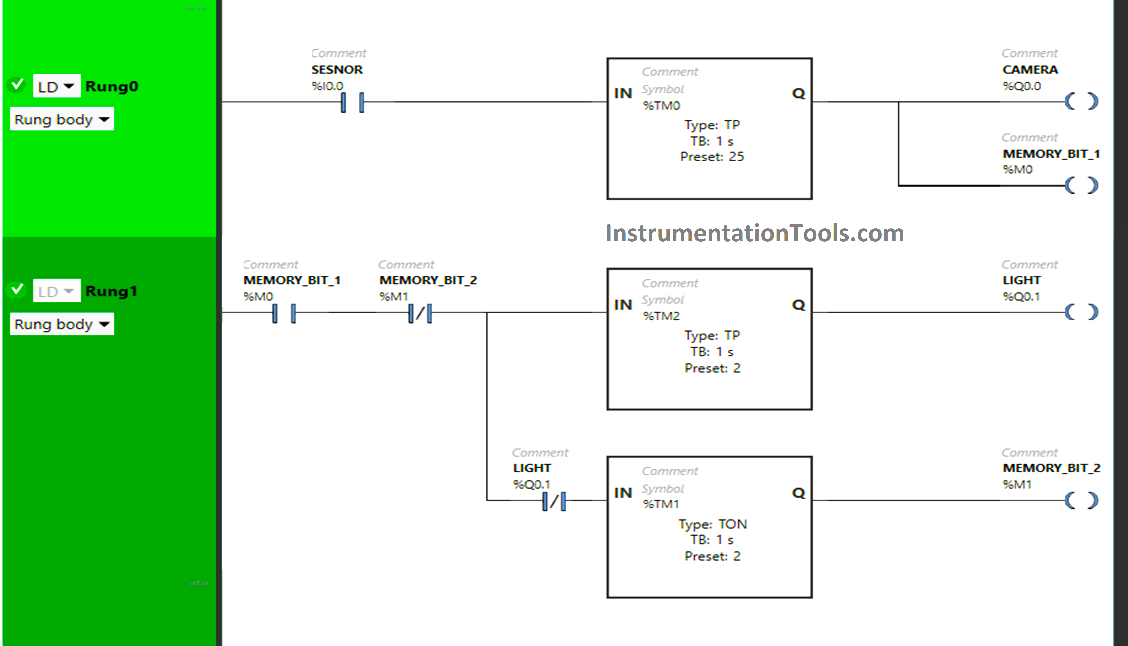
Security Camera Ladder Logic
PLC Timer Application in Security Camera Recording

Program Explained

We have used Normally Open Contact for Sensor (I0.0) and Memory Bit 1 (M0).

In Rung0:

1) Normally Open Contact is used for Sensor (I0.0) to Turn ON  the output Camera (Q0.0) and Memory Bit 1 (M0).

2) Timer Function Block type TP is used to Turn ON the output Camera (Q0.0) and Memory Bit 1 (M0) for a limited time.

In Rung1:

1) Normally Open Contact is used for Memory Bit 1 (M0) to Turn ON the output Light (Q0.1) and Memory Bit 2 (M1).

2) Normally Closed Contact is used for Memory Bit 2 (M1) to turn OFF the output Light (Q0.1) and Memory Bit 2 (M1).

3) Normally Closed Contact is used for Light (Q0.1) to turn ON Memory Bit 2 (M1).

4) Timer Function Block type TP is used to Turn ON the output Light (Q0.1) for a limited time.

5) Timer Function Block type TON is used to delay the turning ON time of Memory Bit 2 (M1) for some time.

Result: When motion is detected

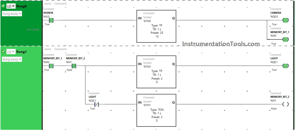
When Senor (I0.0) gets activated (Sensor detects motion),  the output Camera (Q0.0) turns ON (Camera starts recording) and Memory Bit 1 (M0) also turns ON in Rung0 as Normally Open Contact used for Sensor (I0.0) will be in true state and allows the signal to pass through it.

The output Camera (Q0.0) and Memory Bit 1 (M0) turn ON but only for a limited time as Timer Function Block type TP  is used to Turn ON the output Camera (Q0.0) and Memory Bit 1 (M0) for a limited time. The time is set to 45 seconds.
PLC driven camera

After 45 seconds, the output Camera (Q0.0) and Memory Bit 1 (M0) will turn OFF.  When Memory Bit 1 (M0) turns ON in Rung0, Normally Open Contact used for Memory Bit 1 (M0) in Rung1 will be in a True state and allow the signal to pass through it.

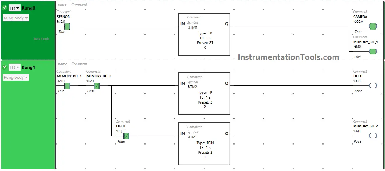
In a false state, Normally Closed Contact used for Memory Bit 2 (M1) also passes the signal to turn ON the output Light (Q0.1). The output Light (Q0.1) turns OFF after some time as Timer Function Block type TP  is used to Turn ON the output Light (Q0.1) for a limited time. The time is set to 2 seconds.
PLC Application Examples of Programming

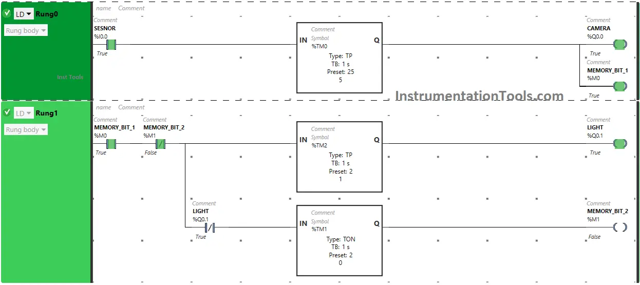
After 2 seconds, the output Light (Q0.1) will turn OFF. When the output Light (Q0.1) turns OFF, Normally Closed Contact used for Light (Q0.1) will be in a false state and pass the signal to turn ON Memory Bit 2 (M1) and Memory Bit 2 (M1) turns ON but after a delay of 2 seconds as Timer Function Block type TON is used to delay the turning ON time of Memory Bit 2 (M1). The time is set to 2 seconds.
PLC Timer example security camera

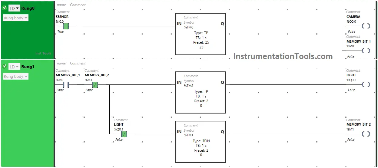
After 2 seconds, Memory Bit 2 (M1) will turn ON but it will turn OFF within no time because in Rung1, Normally Closed Contact is used for Memory Bit 2 (M1). In Rung1, Normally Closed Contact used for Memory Bit 2 (M1) will also turn ON and OFF within no time and the whole process will restart in Rung1.
PLC sensor detects motion and turns lights on and off

In Rung0, when Timer Function Block Type TP reaches its time limit i.e. 25 seconds, the output Camera (Q0.0) will turn OFF ( Camera stops recording) and Memory Bit 1 (M0) will also turn OFF.

As Memory Bit 1 (M0) turns OFF in Rung0, Normally Open Contact used for Memory Bit 1 (M0) in Rung1 will be in a false state and does not allow the signal to pass through it and the whole process stops in Rung1.

If you liked this article, please subscribe to our YouTube Channel for PLC and SCADA video tutorials.

You can also follow us on Facebook and Twitter to receive daily updates.

Read Next:

  • Single-acting Cylinder PLC Logic Operation
  • Free Omron PLC Online Training Course Online
  • User-Defined Data Types and Function Blocks
  • Machine Expert Basic versus Machine Expert
  • How to Configure Distributed IO in a PLC Project?
Don't Miss Our Updates
Be the first to get exclusive content straight to your email.
We promise not to spam you. You can unsubscribe at any time.
Invalid email address
You've successfully subscribed !

Continue Reading

Analog Measurement using Ladder Logic
PLC Ladder Logic Example based on Set Coil and Reset Coil
What is NOR Flash Memory in PLC?
Download Allen Bradley RSLogix PLC Software
DCS
Quiz Program Logic Using PLC Programming
Share This Article
Facebook Whatsapp Whatsapp LinkedIn Copy Link
Share
Leave a Comment

Leave a Reply Cancel reply

Your email address will not be published. Required fields are marked *

Stay Connected

128.3kFollowersLike
69.1kFollowersFollow
210kSubscribersSubscribe
38kFollowersFollow

Categories

Explore More

What is a Annunciator Panel?
How to Train Your Maintenance Team for Industrial Automation Systems?
Waste-Burning System OMRON PLC Program Example
Allen Bradley Powerflex VFD
Produced Tags and Consumed Tags in Studio 5000
Program Flow Control Instructions in PLC Programming
#16 PLC Best Practices – Create Trend for Cycle Time on HMI
Batch Simulator PLC Example Program using LogixPro Simulator

Keep Learning

Network Switch

Network Switch Port Allocation Details

SCADA System Vulnerabilities

SCADA System Vulnerabilities

PLC Data Logging and Transmission

Moving Data between PLCs – Siemens Basics – TSEND TRCV

Siemens SIMATIC S7 PLC GSD File

How to import GSD files into the TIA Portal? – Siemens PLC

PLC Program for Burglar Alarm Security System

PLC Program for Alarm Security System

RSlogix 500 to communicate with Excel

How to Communicate with Excel from RsLinx?

PLC Program to Control Motor Speed using VFD Drive

Motor Speed Control using VFD and PLC Programming

Functional Block Diagram PLC Example for Traffic Light System

Functional Block Diagram PLC Example for Traffic Light System

Learn More

What is a Core Type Transformer

Difference Between Core and Shell Transformers

Solenoid Valve Failure in Plant Start-Up

Solenoid Valve Failure in Plant Start-Up: Identifying the Root Cause

Relay Symbols

Relay circuits

Humidity Sensing Absorption Hydrometer Principle

Humidity Sensing Absorption Hydrometer Principle

Capacitance Pressure Sensor Works

How Capacitive Pressure Sensor Works ?

COCO Simulator

COCO Simulator: Free Process Simulation Software

Communicating Delta PLC Software to Simulator

PLC analog input scaling

PLC Analog Input Scaling

Menu

  • About
  • Privacy Policy
  • Copyright

Quick Links

  • Learn PLC
  • Helping Hand
  • Part Time Job

YouTube Subscribe

Follow US
All rights reserved. Reproduction in whole or in part without written permission is prohibited.
Welcome Back!

Sign in to your account

Username or Email Address
Password

Lost your password?