Learn an example PLC program to control a pump based on level sensors using ladder diagram logic with a video explanation.
Note: The PLC logic example is designed for beginners who are interested to learn the ladder diagrams.
PLC Program to Control a Pump
Problem Statement
Design a PLC ladder logic for the following application.
We are using two level sensors to control the pump. (You can also call them as Level switches in this case).
If the low-level sensor detects the tank is low, then the pump will run for 20 seconds.
If the high-level sensor detects the tank is full, then the pump will stop for 30 seconds.
PLC Learning Series
Our PLC learning series videos are useful for engineers to learn basic PLC programming.
Inputs
The required inputs are listed below.
Low level sensor: I0.0
High level sensor: I0.1
Outputs
The required outputs are listed below.
Pump: Q0.0
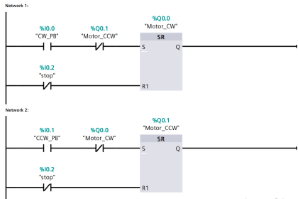
Ladder Diagram Logic
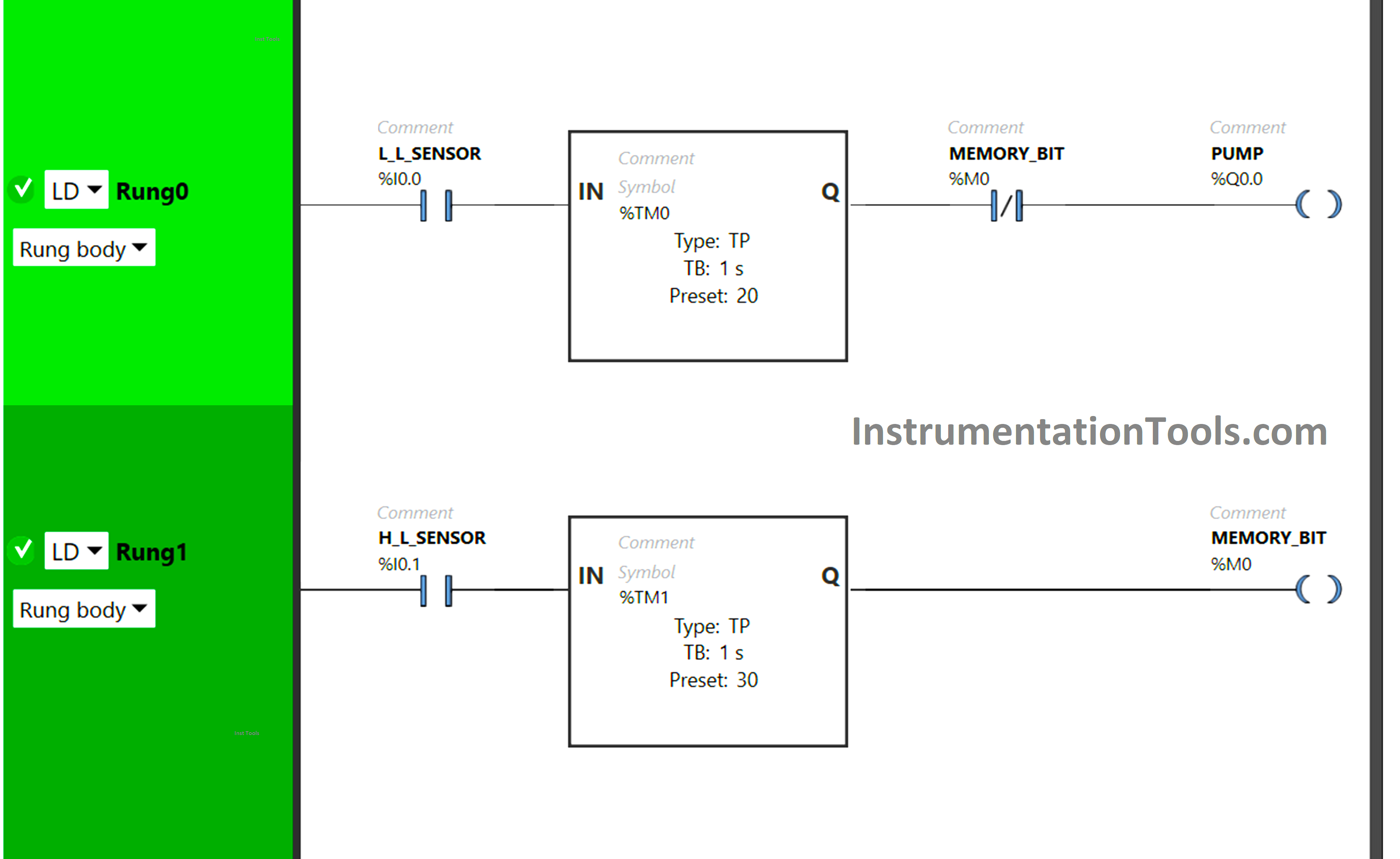
Program Description
We have used Normally Open Contacts for low-level sensor as well as high-level sensor.
We have also used the Normally Closed Contact for Memory (M0) bit in Rung0.
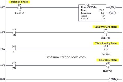
For the Pump, Timer Function Block Type TP is used.
To keep the Pump ON for 20 seconds, Timer Function Block type TP (TM0) is used.
Timer Function Block type TP (TM2) is also used for Memory Bit (M0) to keep it ON for 30 seconds.
To keep the Pump OFF for 30 seconds, Memory Bit taken as Normally Closed Contact in Rung0 is used.
Test Case
Now we simulate our PLC program and see the results.
When the Low-level sensor gets activated (detects the tank is low), the Timer functional block type TP (TM0) will allow the signal to flow for a period of 20 seconds only. (as shown in below image)
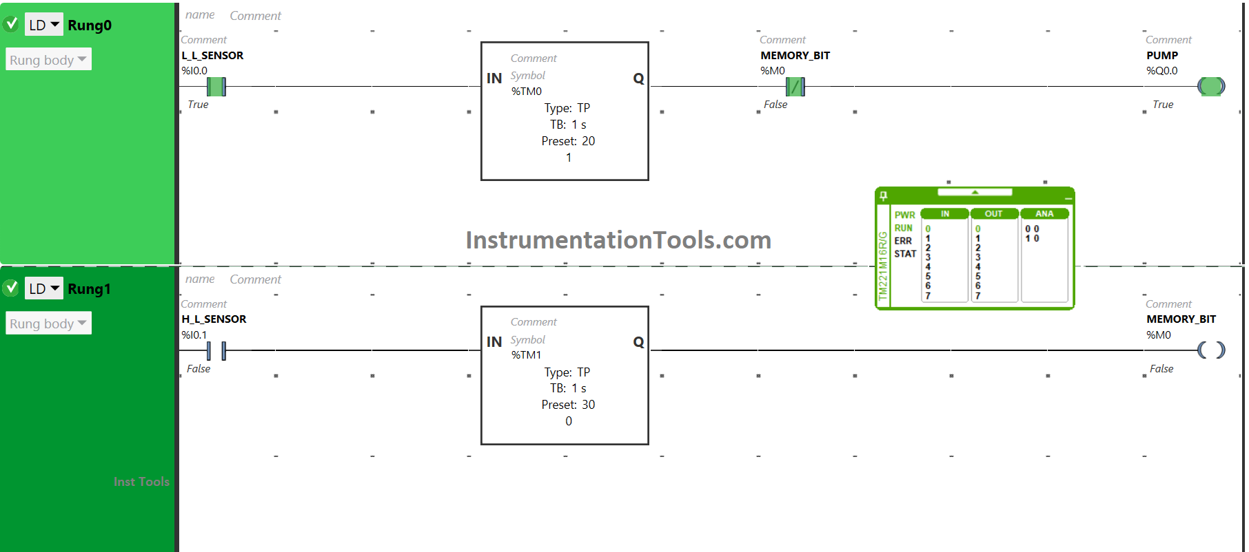
The memory bit (M0) will also allow the signal as it is in a false state. As a result, the Pump will be turned ON. After 20 seconds, the signal will not flow because of the Timer functional block type TP (TM0).
The pump will turn OFF after being ON for 20 seconds.
When a high-level sensor gets activated i.e., when the tank is full, Timer functional block TP (TM1) will allow the signal to flow for an interval of 30 seconds. (as shown in below image)
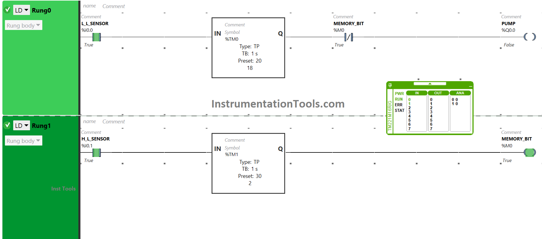
As a result, the Memory bit (M0) will become true only for 30 seconds. Then, in Rung0, the memory bit (M0) used as Normally Closed Contact will not allow a signal for 30 seconds. As a result, the output Pump will turn OFF for a period of 30 seconds.
In a nutshell, when the low-level sensor detects that the level of the tank is low, the pump gets turned ON for 20 seconds and when the high-level sensor detects that the level of the tank is high, the pump gets turned OFF for 30 seconds.
If you liked this article, please subscribe to our YouTube Channel for PLC and SCADA video tutorials.
You can also follow us on Facebook and Twitter to receive daily updates.
Read Next:
- Timers in PLC Programming Tutorials
- Design Ladder Diagram from Boolean Logic
- Electrical Ladder Diagram Control with Timers
- Latching and Unlatching in PLC Programming
- Electrical Cabinet Air Conditioner Maintenance


Not sufficient
1. The Pump is ON when the High Level Switch Makes.
1a. The Pump runs until the Low level Sensor Opens
2. The Pump shuts OFF when the Low Level Switch Opens.