This article explains the basic PLC alarm programming example with 8 switches combination logic to activate an output alarm.
Important: The logic diagram example below is an educational resource for students and engineering graduates to understand PLC essentials.
PLC Alarm Programming
Problem Statement
Design a PLC ladder logic for the following application.
We are using 8 toggle switches to activate an Alarm.
An Alarm is ON when,
- Switch 1 is OFF.
- Switch 2 is ON, or Switch 3 is ON, or both are ON.
- Switch 4 and Switch 5 are both ON.
- One or more of Switches 6,7 and 8 are ON.
Alarm Video
Learn the PLC alarm example tutorial using the below video.
List of PLC Inputs
The required digital inputs are listed below.
Switch 1: I0.0
Switch 2: I0.1
Switch 3: I0.2
Switch 4: I0.3
Switch 5: I0.4
Switch 6: I0.5
Switch 7: I0.6
Switch 8: I0.7
List of PLC Outputs
The required digital outputs are listed below.
Alarm: Q0.0
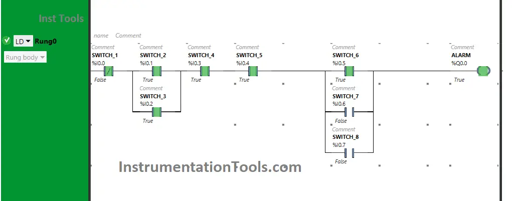
Ladder Diagram for Alarm
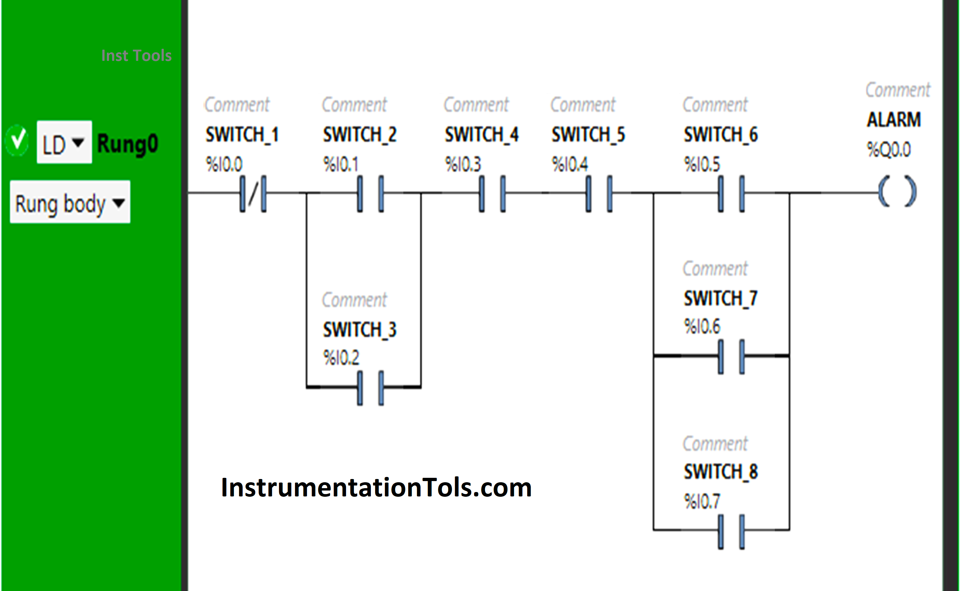
Program Description
We used EcoStruxure Machine Expert Basic PLC software for programming.
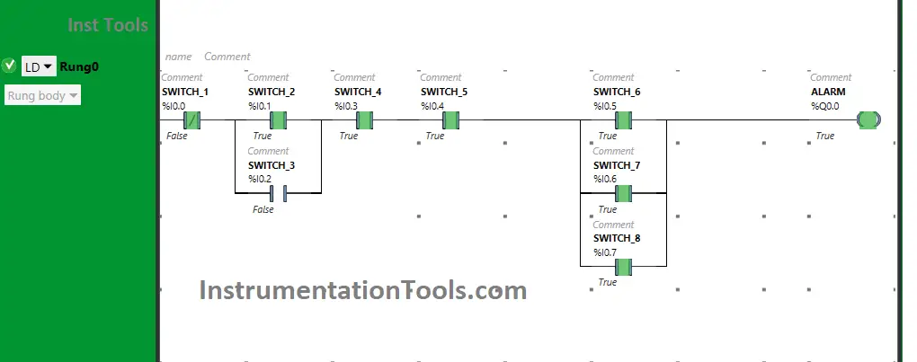
In the above program, we have used Normally Open Contacts as well as Normally Closed Contacts.
Normally Closed Contact is used for Switch 1 and when it is OFF, the Alarm will turn ON.
If Switch 1 is turned ON, the states of the remaining 7 Switches will not matter i.e., the Alarm will be OFF.
Switch 2 (I0.1) and Switch 3 (I0.2) are connected in parallel by implementing OR Logic Gate.
For the Alarm to be ON, one of the two switches i.e., Switch 2 or Switch 3 should be ON.
Switch 4 (I0.3) and Switch 5 (I0.4) are connected in a series that implements AND Logic Gate.
The alarm will TURN ON when both Switch 4 and Switch 5 are turned ON.
If one of the switches i.e., switch 6 or switch 7 or switch 8 is turned ON, the Alarm will TURN ON.
Switch 6 (I0.5), Switch 7 (I0.6), and Switch 8 (I0.7) implement OR Logic Gate as these are connected in parallel.
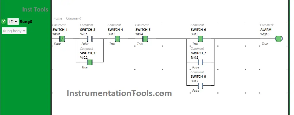
PLC Program Simulation
Here we simulate the program with different inputs. Note: The order of the input switch simulation may be in different sequences in the below results.
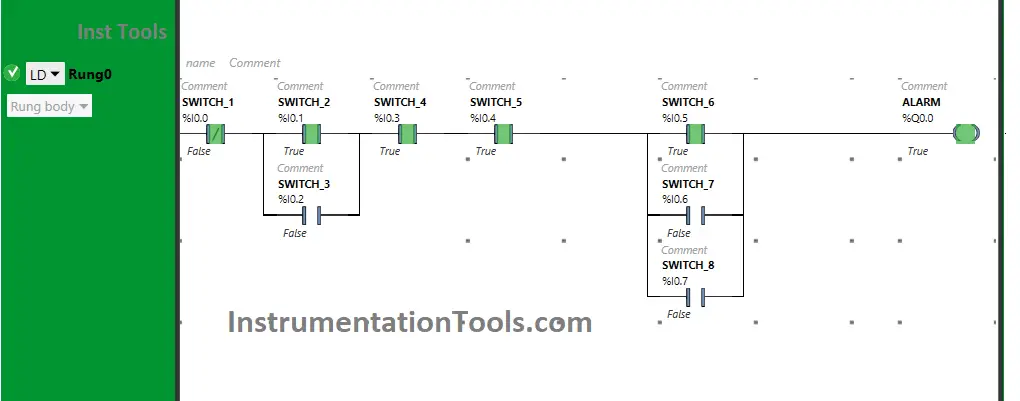
Switch 2 is ON, or Switch 3 is ON, or both are ON

As Switch 2 and Switch 3 are connected in parallel implementing OR Logic Gate, so either Switch 2 or Switch 3 or both Switches, when turned ON will TURN ON the Alarm.
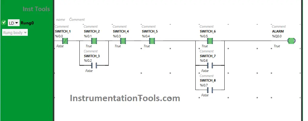
Switch 4 and Switch 5 are both ON
Turning ON both Switch 4 and Switch 5 will TURN ON the Alarm, as these are connected in series implementing AND Logic Gate.
If one of these switches i.e., switch 4 and Switch 5, when turned OFF, the Alarm will turn OFF.
One or more of Switches 6,7 and 8 are ON

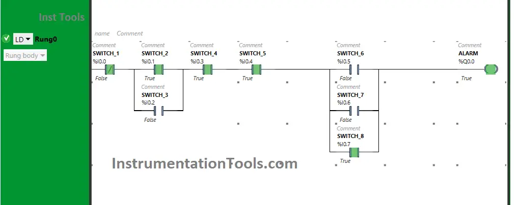
When One or more of Switches 6, 7, and 8 are turned ON, the Alarm will TURN ON as they are connected in parallel implementing OR Logic Gate.
The signal will flow through one of these switches and will reach the output. As a result, the alarm will be ON.
Switch 1 is ON and OFF
The alarm will TURN ON when Switch 1 is OFF as it is in the Normally Closed Contact State (with other switches in the ON state) but if Switch 1 is turned ON, it will not pass the signal to Output.
If you liked this article, please subscribe to our YouTube Channel for PLC and SCADA video tutorials.
You can also follow us on Facebook and Twitter to receive daily updates.
Read Next:
- Log PLC Uptime and Trend it on HMI
- Programmable Logic Controller Test
- Validate PLC Inputs based on Plausibility
- Connecting Allen Bradley PLC and PC
- Advantages of Human-Machine Interface