Single-acting pneumatic cylinders can provide linear motion for a wide range of applications. The single-acting cylinders are essential to industrial automation Unfortunately, the precision and flexibility needed to react to the dynamic conditions of contemporary manufacturing processes are frequently lacking from the current control systems.
The objective is to create a control mechanism that combines two proximity sensors with logical OR operation to improve responsiveness, accuracy, and dependability when operating a single-acting cylinder.
Single-acting Cylinder OR Logic Operation
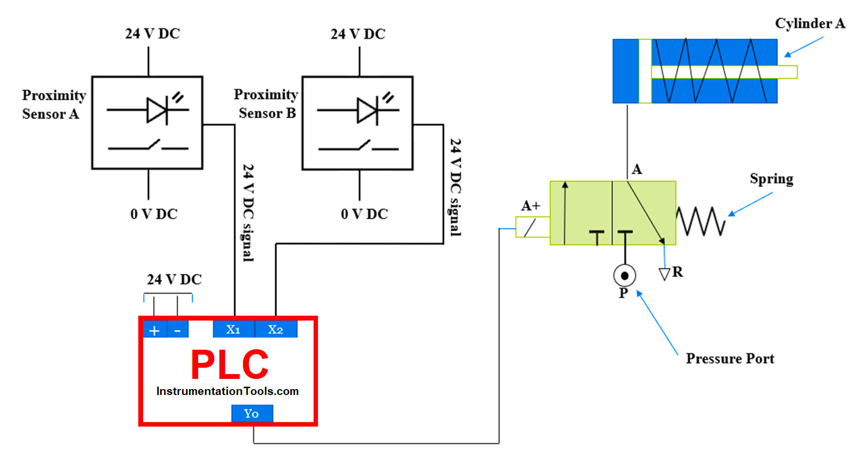
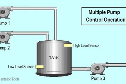
Here as shown in the figure we can see sensor A and sensor B are connected to the PLC controller. Sensor A (X1) relates to the digital input of the programmable controller. Sensor B relates to the programable Logic controller’s other digital input (X1).
Both the sensors have a 24 V DC supply and the programable Logic controller has a 24 V DC supply. Here we have not considered the Programmable Logic controller program part. The solenoid relates to the PLC digital output and solenoid solenoid-operated direction control valve is connected to the single-acting cylinder.
Principle (PLC and Sensors)
Here consider the simple application in which we must operate a single-acting pneumatic cylinder with two proximity sensors. The application is like that so a single-acting pneumatic cylinder will be operated with the sensor operation.
Consider two sensors (Sensor A and Sensor B) related to the programmable controller. The programmable logic controller is programmed with the OR gate logic operation. So, if any one sensor out of the two sensors, hence Sensor A or Sensor B is pressed or sensed then the output will be activated.
In a programmable logic controller, we must write the program so X 1 will get a 24 VDC signal or X2 will get a 24 V DC signal from the field or sensors then it will generate the output and we will get a 24 VDC signal at Y0 output terminal.
Once output is activated supply will go to the solenoid coil and the solenoid coil will be activated. If the solenoid is operated, then due to the internal mechanism plunger will move and the air flow will change.
The direction control valve changes the direction of the air, and it operates the cylinder so the cylinder will move. In this case, if either sensor A is detected, or Sensor B is detected, the Cylinder will be ON and if both are sensed then the output will also be ON. If not, all sensors are detected, then the cylinder will remain in a closed condition.
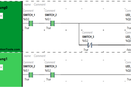
PLC Programming Explanation
As shown in the figure we need to write PLC programming for the application. Here we have two digital inputs sensor A and Sensor B. Both the sensors need to connect with the Programmable logic controller as shown in the main diagram.
Here X1 and X2 are the programmable logic controller addresses for the digital inputs. here we are defining X 0 digital input for the sensor A and X1 digital input for the Sensor B. Both are digital inputs so if the sensor detects any object, then the programmable logic controller will get a 24 VDC signal from the sensors.
If we are getting a signal at X0 it means sensor A is sensing some object. And if we are getting a signal at X1 it means sensor B is sensing some object. As shown in the below figure we will use two digital inputs and one digital output to write the PLC program.
Here the condition is that when one sensor out of both is detecting any object then digital out will be ON. Hence either sensor A or Sensor B is sensing the object then output Y0 will be ON. OR gate we are using for the optional condition so as per the program if we are getting a signal at X0 or X1, Y0 will be energized as per the logic gate condition.
Digital Inputs
Sensor A =X0
Sensor B=X1
Digital Output
Solenoid A+ =Y0
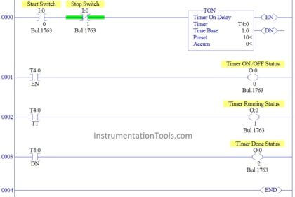
Programmable Logic Controller Ladder Diagram
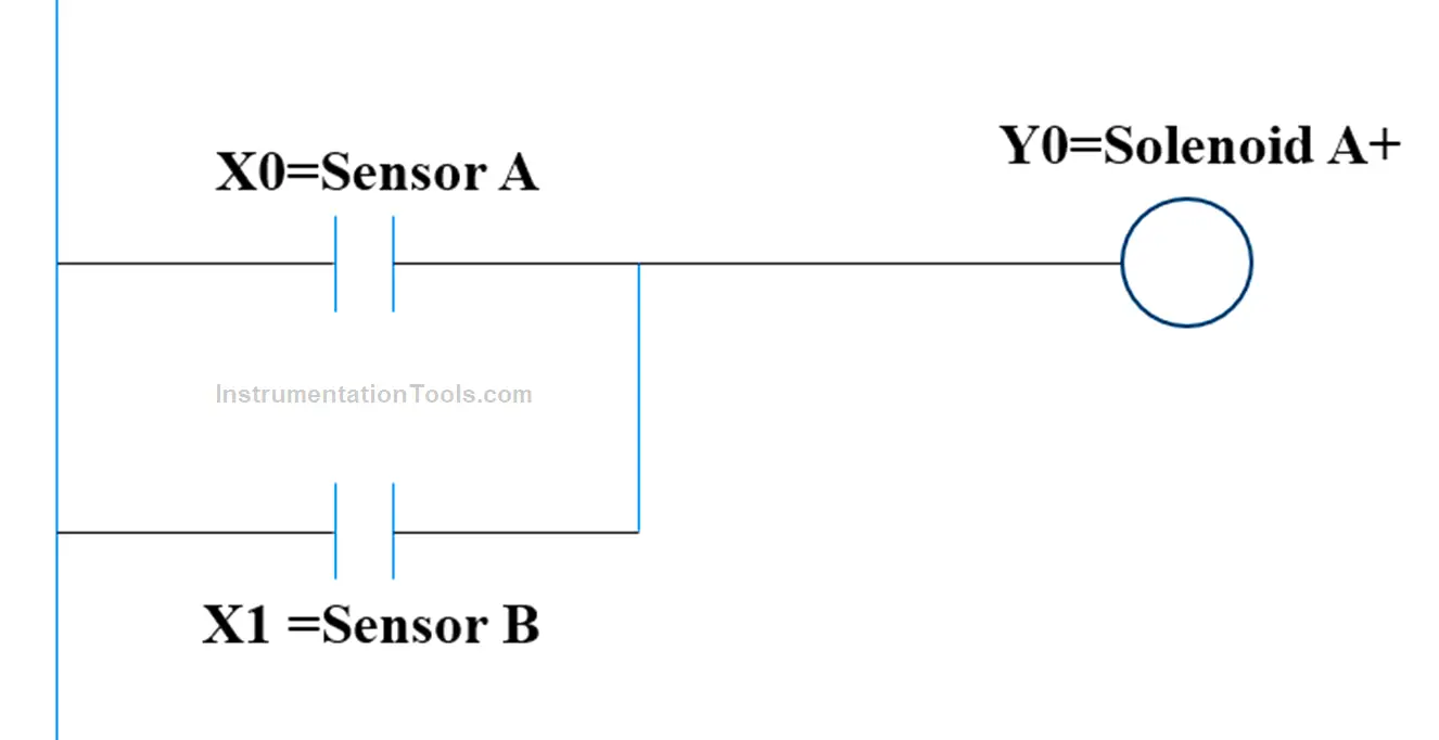
As shown in the ladder diagram, input Sensor A is connected with the digital input X0 and Sensor B is connected with the digital input X1. So, in the Programmable logic controller, we have to define the address for both sensors so the programmable logic controller can identify the inputs that are coming from the field.
We used here OR gate logic or we can say it parallel operation so either X0 or X1 is energized then Y0 will be energized, so at this output terminal, we will get a 24 V DC supply so the solenoid will get a 24 V DC signal and its plunger will move and cylinder will be extracted.
If no detection is happening at any sensor, then the output will remain off and the cylinder will remain in retracted condition.
If you liked this article, then please subscribe to our YouTube Channel for Electrical, Electronics, Instrumentation, PLC, and SCADA video tutorials.
You can also follow us on Facebook and Twitter to receive daily updates.
Read Next:
- Basics of PLC Programming
- Pneumatic Cylinder Air Flow Calculation
- Transferring Data Across PLC Systems
- PLC Programming Example using Switches
- Single-acting Pneumatic Cylinder Operation