Two types of measurement methods are used for tank gauging: volume or mass based.
In a volume based system, level is measured. In a mass based system, the measurement of the hydrostatic pressure of the liquid column is used. The users choice should, therefore, be based on how product inventory is calculated and accounted via volume or weight.
Both methods provide a direct measurement of one factor in the inventory equation, level or pressure. However, bulk storage tanks tend to have large diameters, store products with varying densities that can stratify, and require consideration for high tank levels and overfill protection. A small change in level can make a big difference in accountable volumes (level x diameter), while stratification can lead to level changes that are undetectable by mass based systems. Vendors, therefore, recommends level (volume) based measurement systems.
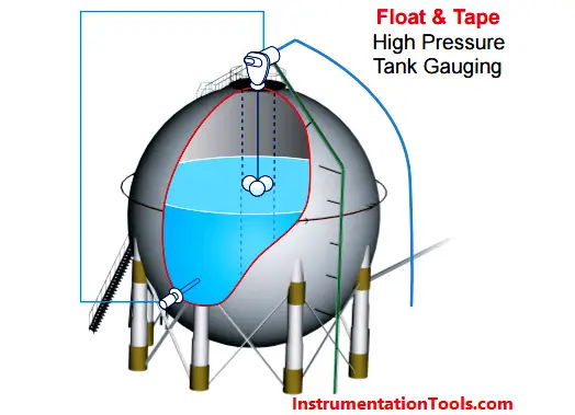
Float & Tape Tank Gauging
Changes in the liquid level inside the tank raise or lower a large stainless steel float. The float is attached to a powerful negator spring via a perforated tape. The negator spring provides constant tension, which balances the float on the liquid level. The perforated tape engages pins on a sprocket wheel that, in turn, drives the counter assembly.
When a gauge board is used to display level in a float & tape system, the negator spring is replaced by a counter weight system. The liquid level in feet and inches or meters and decimeters is displayed on the gauge counter or indicated on a gauge board. This simple design and operation allows the gauge to perform with negligible maintenance throughout its working life.
A range of analog and digital tank gauge transmitters are available that mount directly to mechanical tank gauges. Level measurement data is encoded by the transmitter and output via industry standard communications to the control room.
Some transmitters also offer spot temperature measurement integration that can be used for inventory control applications. When a tank gauge transmitter is used, communications and power are required at the gauge head. Varec transmitters do not require an adaptor flange. When connecting third party equipment, a specific adaptor flange, depending on the transmitter, is often required.
Simplify the process of negator motor replacement and improve the performance of your mechanical tank gauge with a removable Negator Cassette with the negator motor enclosed.
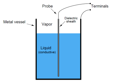
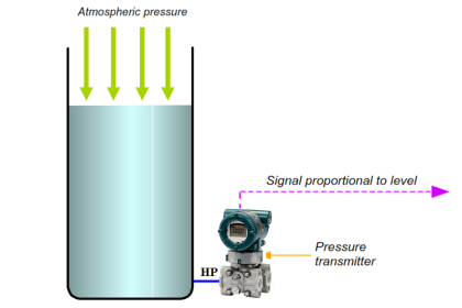
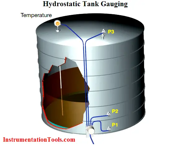
Hydrostatic Tank Gauging
Radar Tank Gauging
Radar tank gauges are “downward-looking” measuring system installed on the tank roof. Operating on the time-of-flight method, they measure the distance from the reference point (process connection) to the product surface. Radar impulses (FMCW principle) are emitted by an antenna, reflected off the product surface and received again by the radar system. The distance to the product surface is proportional to the travel time of the impulse.
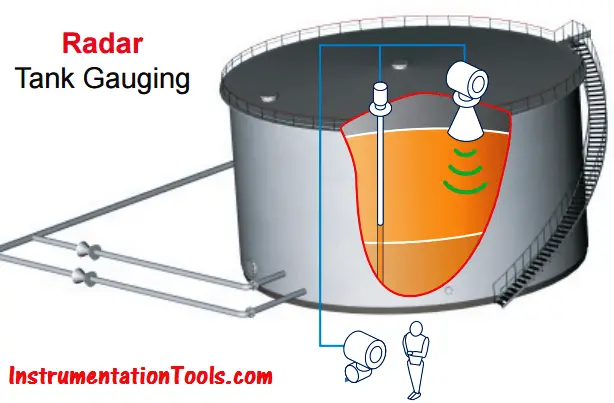
Due to the nature of the microwave, radar tank gauges need to be equipped with functions to suppress interference echoes (e.g. from edges and weld seams) in the tank so they are not interpreted as level measurement. Radar technology is suitable for measuring a wide range of petroleum products.
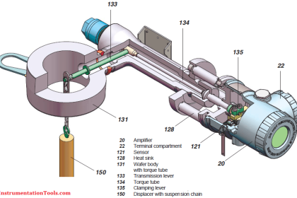
Servo Tank Gauging
servo tank gauges operate on the principle of displacement measurement. A small displacer on a measuring wire is unwound from a drum and accurately positioned in the liquid medium using a servo motor. The weight of the displacer is precisely balanced against a magnetic coupling and the wire drum. When the displacer is lowered and touches the liquid, the weight of the displacer is reduced because of the buoyant force of the liquid.
As a result, the torque in the magnetic coupling is changed and this change is measured by 5 sets of Hall sensors. The signal, an indication of the position of the displacer, is sent to the motor control circuit. As the liquid level rises and falls, the position of the displacer is automatically adjusted by the drive motor. This system provides an outstanding accuracy of +/- 0.7 mm. Servo gauges are ideally suited for light and middle distillates of petroleum.
Hybrid Tank Gauging
Hybrid tank gauging combines an accurate level gauge, temperature sensor(s) and pressure transmitter(s). By utilizing the best of both level based and mass based systems, hybrid tank gauging obtains level, temperature compensated volumes, mass and density measurements.