Inst ToolsInst ToolsInst Tools
  • Ask
  • Courses
  • Videos
  • Q & A
    • Interview
      • Instrumentation
      • Electronics
      • Electrical
      • Practical Questions
    • MCQ
      • Instrumentation MCQ
      • Electrical MCQ
      • Electronics MCQ
      • Control Systems MCQ
      • Analog Electronics MCQ
      • Digital Electronics MCQ
      • Power Electronics MCQ
      • Microprocessor MCQ
      • Multiple Choice Questions
  • EE
    • Electronics
      • Electronics Q & A
      • Electronic Basics
      • Electronic Devices & Circuits
      • Electronics Animation
      • Digital Electronics
    • Electrical
      • Electrical Basics
      • Electrical Q & A
      • Power Electronics
      • Electrical Machines
      • Electrical Animation
      • Power Systems
      • Switchgear & Protection
      • Transmission & Distribution
  • Measure
    • Control Valves
    • Calibration
    • Temperature
    • Pressure
    • Flow
    • Level
    • Analyzers
    • Switches
    • Vibration
    • Solenoid Valve
  • Control
    • PLC Tutorials
    • Control Systems
    • Safety Instrumented System (SIS)
    • Communication
    • Fire & Gas System
  • More
    • Design
    • Tools
    • Animation
    • Basics
    • Formulas
    • Standards
    • TextBooks
    • Common
    • Software
    • Excel Tools
    • Erection & Commissioning
    • Process Fundamentals
    • Videos
    • Books
Search
All rights reserved. Reproduction in whole or in part without written permission is prohibited.
Reading: Difference between Power Cables and Signal Cables
Share
Notification Show More
Font ResizerAa
Inst ToolsInst Tools
Font ResizerAa
  • Courses
  • PLC Tutorials
  • Control Systems
Search
  • Ask
  • Courses
  • Videos
  • Q & A
    • Interview
    • MCQ
  • EE
    • Electronics
    • Electrical
  • Measure
    • Control Valves
    • Calibration
    • Temperature
    • Pressure
    • Flow
    • Level
    • Analyzers
    • Switches
    • Vibration
    • Solenoid Valve
  • Control
    • PLC Tutorials
    • Control Systems
    • Safety Instrumented System (SIS)
    • Communication
    • Fire & Gas System
  • More
    • Design
    • Tools
    • Animation
    • Basics
    • Formulas
    • Standards
    • TextBooks
    • Common
    • Software
    • Excel Tools
    • Erection & Commissioning
    • Process Fundamentals
    • Videos
    • Books
Follow US
All rights reserved. Reproduction in whole or in part without written permission is prohibited.
Inst Tools > Blog > PLC Tutorials > Difference between Power Cables and Signal Cables

Difference between Power Cables and Signal Cables

Signal cables are designed to carry low-level signals and power cables transmit the electrical power needed to operate the equipment.

Last updated: July 15, 2023 2:50 pm
Editorial Staff
PLC Tutorials Electrical Basics
No Comments
Share
6 Min Read
SHARE

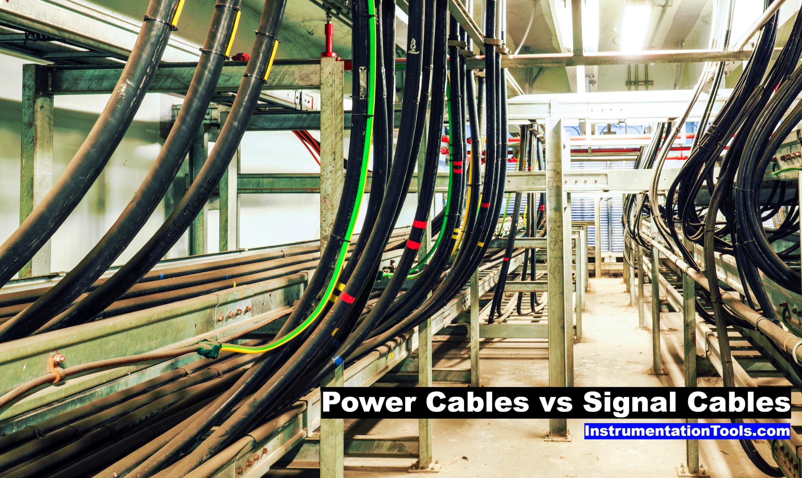
The signal cables and power cables are two types of cables often used in automation systems, each serving a unique purpose. Understanding the difference between power and signal cables can help you determine the right cable for a specific application.

Contents
Signal CablesCharacteristics of Signal CablesPower CablesCharacteristics of Power CablesDifference between Power Cables and Signal CablesConclusion

Signal Cables

Signal cables are integral to the functioning of any modern industrial automation system. Signal cables carry low-level electronic signals between devices or within a device.

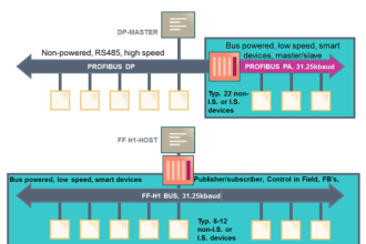
Signal cables facilitate communication in different forms, including data signals, such as Ethernet or Fieldbus communication, and low voltage analog or digital signals, such as 4-20mA current loops or 0-10V signals.

Characteristics of Signal Cables

1. Shielding: Signal cables are typically shielded to protect against electromagnetic interference (EMI), which could corrupt the signal and lead to inaccurate data transfer. The shielding can be a layer of conductive material, usually a type of metal, that surrounds the conductors. This metal layer is grounded, so any interference will be absorbed by the shield and diverted to the ground, instead of affecting the signal.

2. Twisted Pairs: Signal cables often use a configuration known as twisted pairs to reduce interference even further. In a twisted pair, two conductors are twisted around each other at regular intervals. This arrangement helps to reduce the influence of external electromagnetic fields and to minimize cross-talk between signals in different pairs in the same cable.

3. Lower Current Carrying Capacity: As their primary function is signal transmission, these cables are designed for lower current and voltage levels. They are not intended to carry significant power loads.

Power Cables

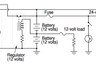
Unlike signal cables, power cables are primarily designed to transmit electrical power. They are used to connect an electrical source to a device or a piece of equipment, delivering the necessary power to operate.

Difference between Power Cables and Signal Cables

Characteristics of Power Cables

1. Higher Current Carrying Capacity: Power cables are constructed to handle higher current and voltage levels. This is a critical feature, as these cables need to safely and effectively transmit the power required to run various equipment and devices.

2. Robust Insulation: Given the higher voltage and current levels, power cables are equipped with robust insulation to protect against electrical faults and to ensure the safety of operators.

3. Variety of Sizes: Power cables come in a variety of sizes, typically denoted by the cross-sectional area of the conductors. The size required depends on the amount of power that needs to be transmitted.

4. May Be Shielded or Unshielded: Depending on the environment and specific application requirements, power cables may also be shielded, particularly if they are used in environments with potential EMI.

Difference between Power Cables and Signal Cables

In the below table, we discussed the comparison between signal and power cables.

DetailsSignal CablesPower Cables
PurposeTransmit low-level electronic signals or data.Transmit electrical power.
Type of ConnectionConnect devices for data or signal transmission.Connect electrical source to devices or equipment.
Current Carrying CapacityLower, since they are for signal transmission.Higher, since they are used to transmit power.
ShieldingTypically shielded to protect against EMI.Can be either shielded or unshielded, based on need.
InsulationStandard insulation for data transmission.Robust insulation to protect against electrical faults.
Conductor ConfigurationOften uses twisted pairs to reduce interference.Variety of sizes to accommodate power transmission needs.
Conductor MaterialUsually composed of copper.Can be aluminum or copper, depending on power needs.
Voltage RatingLower voltage rating.Higher voltage rating.
Physical SizeGenerally smaller and lighter.Generally larger and heavier due to insulation needs.
CostCost depends on data transfer needs and shielding.Cost depends on power capacity, material, and size.
Interference SusceptibilityCan be affected by EMI; hence, often shielded.Connect the electrical source to devices or equipment.
ExamplesData communication, sensor signal transmission, etc.Power supply to machines, motors, transformers, etc.

Conclusion

In conclusion, signal cables and power cables serve fundamentally different purposes. Signal cables are designed to carry low-level signals and ensure reliable communication between devices, while power cables are intended to transmit the electrical power needed to operate the equipment. By understanding these differences, you can select the right type of cable for your specific application, ensuring optimal system performance and safety.

If you liked this article, then please subscribe to our YouTube Channel for Electrical, Electronics, Instrumentation, PLC, and SCADA video tutorials.

You can also follow us on Facebook and Twitter to receive daily updates.

Read Next:

  • Single Core and Multi-Core Cables
  • Difference Between HV and LV Cables
  • Types of Cables in Industrial Automation
  • Instrumentation Cables Testing Steps
  • Flame Resistant and Retardant Cables
Don't Miss Our Updates
Be the first to get exclusive content straight to your email.
We promise not to spam you. You can unsubscribe at any time.
Invalid email address
You've successfully subscribed !
Use of Regions in SCL Language
PLC Programming for Pumping and Draining System
What is Marshalling Cabinet?
Ladder Logic Vs. Other Programming Languages – PLC Basics
Why is IGBT used in VFD?
Share This Article
Facebook Whatsapp Whatsapp LinkedIn Copy Link
Share
Leave a Comment

Leave a Reply Cancel reply

Your email address will not be published. Required fields are marked *

Stay Connected

128.3kFollowersLike
69.1kFollowersFollow
208kSubscribersSubscribe
38kFollowersFollow

Categories

Recent Comments

  • Kamli on Top Free PLC Software
  • Guifty Shimica on Top Non-PLC Certification Courses for Automation Professionals
  • Guifty Shimica on Top Non-PLC Certification Courses for Automation Professionals
  • MIHARITSOA Aina Sitraka on Top Non-PLC Certification Courses for Automation Professionals

Related Articles

PLC Ladder Logic for Demultiplexer

1 to 8 Demultiplexer PLC ladder diagram

Basics of PID Controllers

PID Controllers in Closed Loop Control Systems – PLC Basics

Instrument Cable

Difference Between Power Cable and Instrument Cable

Sample Schematic Template for Systems Architecture Diagram

Design Document for Project Systems Architecture

Types of MCB

Types of MCB

Types of Scan Time in a PLC

#16 PLC Best Practices – Create Trend for Cycle Time on HMI

User Defined Function Blocks in PLC

What are User Defined Function Blocks in PLC?

Database in Siemens PLC

Steps to Configure TCP/IP Communication in Siemens S7-1200 PLC

More Articles

Industrial Automation Sales and Marketing Tools

Industrial Automation Sales and Marketing Tools

Safety Instrumented System Interview Questions Answers

Safety Instrumented System Interview Questions and Answers

Radar Level Transmitter in Briddle level Measurement

Radar Level Transmitter in Briddle level Measurement

Electromagnetic

Types of Signals Based on Electromagnetic Compatibility (EMC Performance)

Common Control Valve Problems

Troubleshooting Common Control Valve Problems

How to Connect HART Communicator with DP Transmitter

15 HART Communicator Questions

Electronic Devices & Circuits Objective Questions

Electronic Devices & Circuits Quiz – Set 1

RF-Capacitance Level Switch Principle

RF Capacitance Level Switch Working Principle

Follow US
All rights reserved. Reproduction in whole or in part without written permission is prohibited.
Welcome Back!

Sign in to your account

Username or Email Address
Password

Lost your password?