Inst ToolsInst ToolsInst Tools
  • Ask
  • Courses
  • Videos
  • Q & A
    • Interview
      • Instrumentation
      • Electronics
      • Electrical
      • Practical Questions
    • MCQ
      • Instrumentation MCQ
      • Electrical MCQ
      • Electronics MCQ
      • Control Systems MCQ
      • Analog Electronics MCQ
      • Digital Electronics MCQ
      • Power Electronics MCQ
      • Microprocessor MCQ
      • Multiple Choice Questions
  • EE
    • Electronics
      • Electronics Q & A
      • Electronic Basics
      • Electronic Devices & Circuits
      • Electronics Animation
      • Digital Electronics
    • Electrical
      • Electrical Basics
      • Electrical Q & A
      • Power Electronics
      • Electrical Machines
      • Electrical Animation
      • Power Systems
      • Switchgear & Protection
      • Transmission & Distribution
  • Measure
    • Control Valves
    • Calibration
    • Temperature
    • Pressure
    • Flow
    • Level
    • Analyzers
    • Switches
    • Vibration
    • Solenoid Valve
  • Control
    • PLC Tutorials
    • Control Systems
    • Safety Instrumented System (SIS)
    • Communication
    • Fire & Gas System
  • More
    • Design
    • Tools
    • Animation
    • Basics
    • Formulas
    • Standards
    • TextBooks
    • Common
    • Software
    • Excel Tools
    • Erection & Commissioning
    • Process Fundamentals
    • Videos
    • Books
Search
All rights reserved. Reproduction in whole or in part without written permission is prohibited.
Reading: How to Create Calibration Records?
Share
Notification Show More
Font ResizerAa
Inst ToolsInst Tools
Font ResizerAa
  • Courses
  • PLC Tutorials
  • Control Systems
Search
  • Ask
  • Courses
  • Videos
  • Q & A
    • Interview
    • MCQ
  • EE
    • Electronics
    • Electrical
  • Measure
    • Control Valves
    • Calibration
    • Temperature
    • Pressure
    • Flow
    • Level
    • Analyzers
    • Switches
    • Vibration
    • Solenoid Valve
  • Control
    • PLC Tutorials
    • Control Systems
    • Safety Instrumented System (SIS)
    • Communication
    • Fire & Gas System
  • More
    • Design
    • Tools
    • Animation
    • Basics
    • Formulas
    • Standards
    • TextBooks
    • Common
    • Software
    • Excel Tools
    • Erection & Commissioning
    • Process Fundamentals
    • Videos
    • Books
Follow US
All rights reserved. Reproduction in whole or in part without written permission is prohibited.
Inst Tools > Blog > Calibration > How to Create Calibration Records?

How to Create Calibration Records?

The calibration record is the proof that the instrument was calibrated on the mentioned date & time. Learn how to create it.

Last updated: June 10, 2022 12:26 pm
Editorial Staff
Calibration
No Comments
Share
4 Min Read
SHARE

Instrumentation engineers do maintenance and calibration of various field instruments.

Contents
Calibration RecordsPressure Transmitter Calibration Record

We do carry out preventive maintenance as well as corrective maintenance of field instruments like control valves, on-off valves, pressure transmitters, flow transmitters, level transmitters, temperature transmitters, fire & gas detectors, and analyzers, etc.

After job completion, we have to fill up a calibration record for that particular instrument.

The calibration record is the proof that the instrument was calibrated on the mentioned date & time and the result of the calibration can be found in the calibration record. This calibration record is needed as per IMS policies and other approvals also.

Calibration Records

We need the below-mentioned data for the creation of the calibration record.

  1. Exact tag number of the instrument as per your system policy (SAP system or any other system being followed at your plant).
  2. Location or the area in which the instrument is installed.
  3. Order number on which the job is assigned. (or any specific PM job details)
  4. The date & time on which the job is carried out. (Don’t use the order generation date here).
  5. Range of the instrument as per the datasheet. In the case of a differential pressure type flow transmitter, we need two ranges i.e. the differential pressure in mmH2O and flow rate in m3/hr. (or any other units)
  6. Maximum permissible error in %. (It is required to validate the calibration result)
  7. Note down the readings before starting the PM job and readings after completion of the PM job.
  8. Note down the response of the instrument in terms of range in 0%, 25%, 50%, 75%, and 100% in an increasing manner and also similarly in decreasing manner.
  9. The sample calibration excel sheet is provided. It will automatically calculate the error in %.
  10. Here we are supposed to enter values if our instrument is having errors more than the maximum permissible error. One before calibration and one after calibration.
  11. A different area is provided for switches like vibration switch, level switch, pressure switch, flow switch, and temperature switch. Always test the switch more than two times.
  12. We also need to maintain the record of the gas cylinders we used for calibrating any analyzer or the gas detector. A column for that is also present in the calibration sheet.
  13. Details of TCI also needs to be filled up for reference purpose.
  14. The calibration sheet also contains a column where we can enter other job details. Details like some corrosion observed, installation not proper, proper approach not available, and spares consumed can be added here.
  15. At last, we need to enter the details of the persons who are involved in the PM job.

Download Calibration Record in Excel: Click Here

Pressure Transmitter Calibration Record

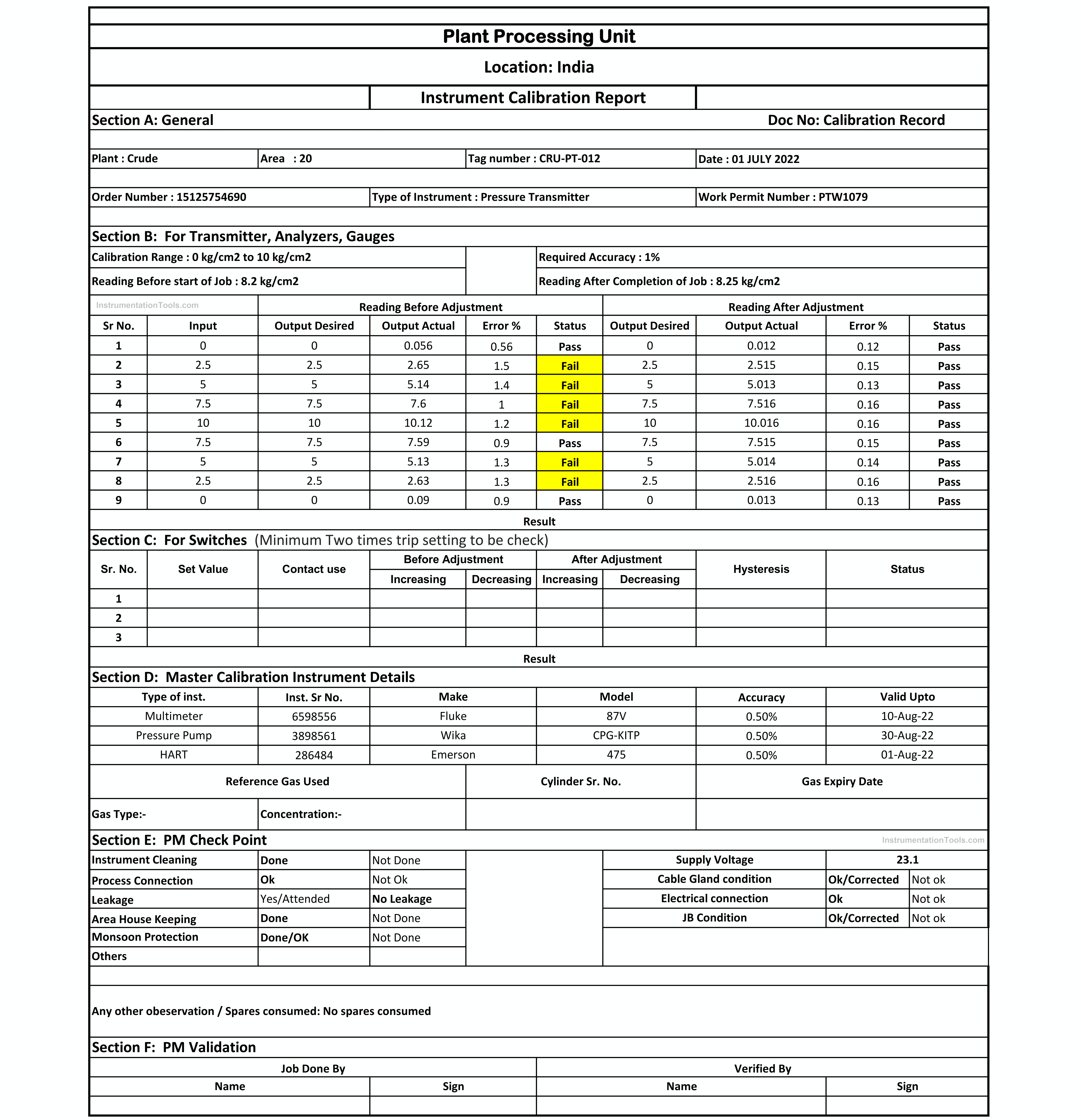
A sample copy filled up for a pressure transmitter can be seen. This pressure transmitter was not having a proper response during the PM job i.e. error was greater than the maximum permissible error. Hence, we calibrated the pressure transmitter.
Calibration Record
Don't Miss Our Updates
Be the first to get exclusive content straight to your email.
We promise not to spam you. You can unsubscribe at any time.
Invalid email address
You've successfully subscribed !
Thermocouple Calibration
Infrared Hydrocarbon Gas Detector Calibration Procedure
Instrument Maintenance and Calibration System
Electrical Standards
Selection of Master Instrument for Calibration
Share This Article
Facebook Whatsapp Whatsapp LinkedIn Copy Link
Share
Leave a Comment

Leave a Reply Cancel reply

Your email address will not be published. Required fields are marked *

Stay Connected

128.3kFollowersLike
69.1kFollowersFollow
208kSubscribersSubscribe
38kFollowersFollow

Categories

Recent Comments

  • Kamli on Top Free PLC Software
  • Guifty Shimica on Top Non-PLC Certification Courses for Automation Professionals
  • Guifty Shimica on Top Non-PLC Certification Courses for Automation Professionals
  • MIHARITSOA Aina Sitraka on Top Non-PLC Certification Courses for Automation Professionals

Related Articles

pH Analyzer Calibration and Troubleshooting

pH Analyzer Calibration and Troubleshooting

Multiphase Flow Meter Calibration Procedure

Multiphase Flow Meter Calibration Procedure

Turbidity Sensor Calibration Procedure

Turbidity Sensor Calibration Procedure

Closed-tank-DP-Level-Transmitter-with-wet-leg-elevation-zero-direct-mount-Calibration

Closed tank DP Level Transmitter with wet leg elevation zero direct mount Calibration

Calibration Instruments

Basics of Calibration

DP type Flow Transmitter Calibration

DP type Flow Transmitter Preventive Maintenance and Calibration

Temperature-gauge-calibration

Temperature Sensor calibration procedure

Differential Pressure Switch Calibration Procedure - Copy

Differential Pressure Switch Calibration Procedure

More Articles

Pressure instruments example circuit

Motion-Balance and Force-Balance Instruments

Control Panels Material Take-Off (MTO)

Control Panels Material Take-Off (MTO) – Engineering Project

Electrical Drives and Controls Interview Questions

Electrical Drives and Controls Interview Questions

Pressure Switch Questions

Pressure Switch Questions

Selecting A Pneumatic Manifold

How to Select a Pneumatic Manifold

Bathtub curve

Bathtub Curve

Split Phase Motor

Single Phase AC Induction Motors

PLC Ladder Logic Door Open and Closing System

Which Language is Best for PLC Programming?

Follow US
All rights reserved. Reproduction in whole or in part without written permission is prohibited.
Welcome Back!

Sign in to your account

Username or Email Address
Password

Lost your password?