Inst ToolsInst ToolsInst Tools
  • Courses
  • Automation
    • PLC
    • Control System
    • Safety System
    • Communication
    • Fire & Gas System
  • Instrumentation
    • Design
    • Pressure
    • Temperature
    • Flow
    • Level
    • Vibration
    • Analyzer
    • Control Valve
    • Switch
    • Calibration
    • Erection & Commissioning
  • Interview
    • Instrumentation
    • Electrical
    • Electronics
    • Practical
  • Q&A
    • Instrumentation
    • Control System
    • Electrical
    • Electronics
    • Analog Electronics
    • Digital Electronics
    • Power Electronics
    • Microprocessor
  • Request
Search
  • Books
  • Software
  • Projects
  • Process
  • Tools
  • Basics
  • Formula
  • Power Plant
  • Root Cause Analysis
  • Electrical Basics
  • Animation
  • Standards
  • 4-20 mA Course
  • Siemens PLC Course
Reading: Captive Power Plant Trip Root Cause Analysis
Share
Notification Show More
Font ResizerAa
Inst ToolsInst Tools
Font ResizerAa
  • Courses
  • Design
  • PLC
  • Interview
  • Control System
Search
  • Courses
  • Automation
    • PLC
    • Control System
    • Safety System
    • Communication
    • Fire & Gas System
  • Instrumentation
    • Design
    • Pressure
    • Temperature
    • Flow
    • Level
    • Vibration
    • Analyzer
    • Control Valve
    • Switch
    • Calibration
    • Erection & Commissioning
  • Interview
    • Instrumentation
    • Electrical
    • Electronics
    • Practical
  • Q&A
    • Instrumentation
    • Control System
    • Electrical
    • Electronics
    • Analog Electronics
    • Digital Electronics
    • Power Electronics
    • Microprocessor
  • Request
Follow US
All rights reserved. Reproduction in whole or in part without written permission is prohibited.
Inst Tools > Blog > Root Cause Analysis (RCA) > Captive Power Plant Trip Root Cause Analysis

Captive Power Plant Trip Root Cause Analysis

In this article, we will learn the captive power plant (CPP) trip root cause analysis. It is equipped with Frame-V Gas Turbine Generators.

Last updated: November 3, 2021 7:09 pm
Editorial Staff
Root Cause Analysis (RCA)
No Comments
Share
5 Min Read
SHARE

The captive power plant (CPP) in the Onshore Gas Terminal (OGT) is set up to meet the power and steam requirements of the process and utility systems in the OGT complex.

Contents
Incident SummaryProbable CausesObservationsRoot Cause AnalysisMeasures to avoid such incidents in futureDocuments and Reports

The CPP is equipped with two M/S GE make Frame-V Gas Turbine Generators (GTG) of capacity 20.5 MW each; both the GTGs would be in operation each operating at part load as per the design philosophy.

The hot flue gas from each GTG is diverted to the respective HRSG (Heat Recovery Steam Generator) to produce process steam.

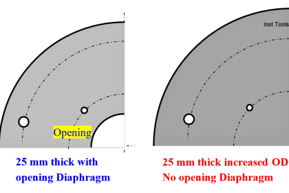
Each HRSG is equipped with a supplementary firing system and is designed to meet the peak load of 66 TPH of High-Pressure steam generation (36 Kg/cm, 256 Deg°C).

Both the HRSGs would be operating at part load. CPP is also equipped with fuel gas conditioning skids to ensure the quality of fuel gas used in GTG.

Recently the Captive power plant has tripped on —DATE— at 05.55 hrs on electrical protection (earth fault).

Incident Summary

On —date— Gas turbine-2 which was running at normal operating conditions tripped due to electrical protection generated from generator relay protection panel at 05.55 hrs lead to production loss.

The generator is provided with electrical protection on stator earth fault of 1N>1. EDG failed to start automatically due to PMCC-1 (Emergency PMCC) normal incomers didn’t trip during a blackout.

The incomers were switched on manually and the Emergency diesel generator was started.

Captive Power Plant Trip Root Cause Analysis

Probable Causes

  1. Actual earth fault in generator stator winding.
  2. Malfunction of the current sensing device.
  3. Transient earth fault in the downstream electrical system.

Observations

  1. The generator relay protection given a trip command on electrical  protection (stator earth fault 1N> 1)
  2. The trip valve setting in  generator  protection  relay (MICOM) for stator earth fault is 5Amps with 600 milli seconds delay.
  3. The actual current sensed by the protection system was 88Amps.
  4. The  generator  panels  were  physically  inspected  for  any  fault  and  there  is  no significant evidence for short circuit founed.
  5. The CT was physically checked and found to be good.
  6. Generator differential protection relay not operated.
  7. 11KV bus differential relay is not operated.
  8. No alarm/tripping indication in downstream electrical distribution systems

Root Cause Analysis

  1. From  the  observations  above,  it  is  derived  that  the  probable  causes  1 and  2 mentioned above is not the reason for this trip.
  2. Further to ascertain the healthiness of the generator stator,  the generator excitation was kept on manual  and excitation voltage was slowly and gradually increased up to
  3. 11KV and there is no abnormality observed.
  4. As there no alarm/tripping  in the downstream electrical distribution system, the exact point of fault remains uncertain. The trip may be due to transient fault initiated from generator downstream electrical system.

Measures to avoid such incidents in future

  1. Relay calibration and testing to be carried out in complete electrical system.
  2. Over  all  Relay  coordination  study  for  longest  chain  in  OGT  (CPP  substation  to substation)  needs to be carried  out and final  relay setting  recommendation  of the study is to be implemented.
  3. Through inspection for possible entry for rodents in the entire electrical  system to be carried out
  4. Regular pest control in all electrical systems to be carried out.

Documents and Reports

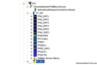
Mark Vie system sequence of events

If you liked this article, then please subscribe to our YouTube Channel for Instrumentation, Electrical, PLC, and SCADA video tutorials.

You can also follow us on Facebook and Twitter to receive daily updates.

Read Next:

  • Trip Valve Principle
  • Erratic Radar Level Gauge
  • Basics of Alarms and Trip
  • Choked Control Valve Trim Cage
  • Amine Pump Root Cause Analysis
Don't Miss Our Updates
Be the first to get exclusive content straight to your email.
We promise not to spam you. You can unsubscribe at any time.
Invalid email address
You've successfully subscribed !

Continue Reading

Learnings from the BP Refinery Explosion at Texas City
Cooling Water Circulating Pump Low throughput Resolved
Root Cause Analysis for Tank Overflow due to Valve Problem
Hunting of Control Valves
Phosphate Dozing System Problems
An Indian Plants all turbines’ low Vacuum & Saudi Plant turbo-compressor only
Share This Article
Facebook Whatsapp Whatsapp LinkedIn Copy Link
Share
Leave a Comment

Leave a Reply Cancel reply

Your email address will not be published. Required fields are marked *

Stay Connected

128.3kFollowersLike
69.1kFollowersFollow
210kSubscribersSubscribe
38kFollowersFollow

Categories

Explore More

Incident Investigation: Motor Operated Valve Lesson
Fan Motor Frequent Journal Bearing Failures Posed Plant Outages
Failing Weigh Feeders and Mechanical Variable Speed Drives (VSD)
RCA – Compressor Did Not Trip on Suction Pressure Low Low
Turbine Flow Meter (TFM) Field Calibration Uncommon Request
Amine Pump Trip – Root Cause Analysis
Rotary Granulator Drive Root Cause Analysis (RCA)
Seawater Pipeline Spools from day-1 leaks threaten Plant Shutdown

Keep Learning

Single Bearing Motor Stator Winding

Critical High KiloWatt Motor Winding Burnout Threats

Centrifugal Compressor Shaft Vibrations Problem

Centrifugal Compressor near ½-RPM Frequency High Magnitude Shaft Vibrations

Wrongly terminated Thermocouple (TC) wires

Too Low-Temperature Readings after a Failed Thermocouple Change

Arc Fault Breaker (AFB) Electrical Problem Solved

Premature Arc Fault Breaker Failures

Erratic Stroking Control Valves

Erratic Stroking Control Valves Delaying the Shutdown Plant Restart

Tilting Pad Bearing

8000 RPM 8000 kW Turbine Problem

Burst Transformers Root Cause Analysis

Burst Transformer – Electrical Problem Solved

Pressure Correction Pneumatic Instrumentation

Pressure Correction Pneumatic Instrumentation

Learn More

Difference between Stepper Motor and DC Motor

Difference between Stepper Motor and DC Motor

Proximity Switch Working Animation

Proximity Switch Working Animation

Instrumentation Books Free Download

Instrumentation Books Download

Automatic Liquid Mixing Application

PLC Program for Automatic Liquid Mixing Application

Power Systems Questions & Answers

Power Systems MCQ Series 13

Hazardous Area Terminology

Hazardous Area Terminology

Inspection and Testing of Fiber Optic Cable

Inspection and Testing of Fiber Optic Cable

Power Systems Operation and Control Interview questions

Power Systems Operation and Control Interview questions

Menu

  • About
  • Privacy Policy
  • Copyright

Quick Links

  • Learn PLC
  • Helping Hand
  • Part Time Job

YouTube Subscribe

Follow US
All rights reserved. Reproduction in whole or in part without written permission is prohibited.
Welcome Back!

Sign in to your account

Username or Email Address
Password

Lost your password?