Learn the testing procedure for the field instruments impulse line, pipe, or tubing pressure leak test.
Contents
Test Pressure Equipment
- Test gauge, Hydro manual pump, Hose
- Guage used shall be calibrated +/- 1% accuracy and shall have valid calibrate stickers
Test Medium
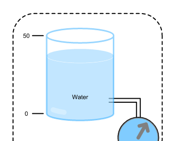
- Clean water
- Air
Testing Pressure
- The test pressure equipment shall be 1.5 times of the max. working pressure
- Incase of pneumatic test, test pressure shall be 1.1 times
Checks To Be Carried Out Before Starting Pressure Test
- Ensure that ferrules are correctly installed
- Impulse lines shall be supported and slope maintained properly
- Ensure that instrument connected is isolated
- Barricade the area for hydro test access shall restrict to authorized persons only
- Use all safety PPE’s ( Personal Protective Equipments)
Impulse Line Testing Procedure
- After verifying the completeness of all above applicable records line shall be cleared for the pressure test
- Avoid air pocket for mention vents at high points shall be left open and not closed until clean test medium flow from the outlet
- If leaks are observed in the line, marks these leaks and de-pressurize the line
- Before starting repairs, ensure that the lines shall be drained properly
- If any repairs have been carried out, this line shall be re-pressurize tested, and documented
Post Testing Procedure
- De-pressurization of the line shall be carried out in a controlled manner
- Immediately release of pressure is not permitted
- These lines are to be drained out and air flushed after testing
Final Checks to be Carried Out
- All the tubes are to be properly cleaned by using compressed air
- Check that all connections are done properly.
Read Next: