Inst ToolsInst ToolsInst Tools
  • Courses
  • Automation
    • PLC
    • Control System
    • Safety System
    • Communication
    • Fire & Gas System
  • Instrumentation
    • Design
    • Pressure
    • Temperature
    • Flow
    • Level
    • Vibration
    • Analyzer
    • Control Valve
    • Switch
    • Calibration
    • Erection & Commissioning
  • Interview
    • Instrumentation
    • Electrical
    • Electronics
    • Practical
  • Q&A
    • Instrumentation
    • Control System
    • Electrical
    • Electronics
    • Analog Electronics
    • Digital Electronics
    • Power Electronics
    • Microprocessor
  • Request
Search
  • Books
  • Software
  • Projects
  • Process
  • Tools
  • Basics
  • Formula
  • Power Plant
  • Root Cause Analysis
  • Electrical Basics
  • Animation
  • Standards
  • 4-20 mA Course
  • Siemens PLC Course
Reading: Thermocouple Details
Share
Notification Show More
Font ResizerAa
Inst ToolsInst Tools
Font ResizerAa
  • Courses
  • Design
  • PLC
  • Interview
  • Control System
Search
  • Courses
  • Automation
    • PLC
    • Control System
    • Safety System
    • Communication
    • Fire & Gas System
  • Instrumentation
    • Design
    • Pressure
    • Temperature
    • Flow
    • Level
    • Vibration
    • Analyzer
    • Control Valve
    • Switch
    • Calibration
    • Erection & Commissioning
  • Interview
    • Instrumentation
    • Electrical
    • Electronics
    • Practical
  • Q&A
    • Instrumentation
    • Control System
    • Electrical
    • Electronics
    • Analog Electronics
    • Digital Electronics
    • Power Electronics
    • Microprocessor
  • Request
Follow US
All rights reserved. Reproduction in whole or in part without written permission is prohibited.
Inst Tools > Blog > Temperature Measurement > Thermocouple Details

Thermocouple Details

Learn all the details of temperature measuring element thermocouple sensor wiring, standard, tolerance, and troubleshooting.

Last updated: September 19, 2020 11:16 am
Editorial Staff
Temperature Measurement
2 Comments
Share
4 Min Read
SHARE

Thermocouple wiring

  • The thermocouple extension wire should meet the requirements of ISA/ANSI MC96.1 or IEC-60584.
  • Thermocouple signals are low-level signals that should be properly shielded and grounded to prevent noise interference with the signal.
  • Insulated hot junctions shall have an insulation resistance to ground of 50 megohms minimum at ambient temperature and 2 megohms minimum at 4508C (8508F).
  • Terminals within the head shall be clearly marked ‘+’, ‘-’, ‘ground’, as appropriate.
  • The multi circuits within heads shall be clearly identified
  • Check that the polarity and continuity of the lead wires are consistent through all the junction boxes from the thermocouple head to the control center

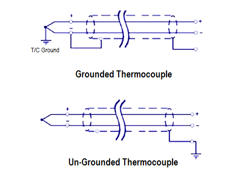
Grounded Thermocouple

  • For grounded thermocouples, check that the shield wire is terminated at the grounded thermocouple head in accordance with the manufacturer’s instructions and not at the shield connection on the control center or instrument terminals

Grounded and Ungrounded Thermocouples

Contents
Thermocouple wiringGrounded ThermocoupleUn-Grounded ThermocoupleThermocouple Color CodesThermocouple ToleranceThermocouple StandardThermocouple Troubleshooting

Un-Grounded Thermocouple

  • For ungrounded thermocouples, check that the shield wire is terminated in the control room.
  • Grounding of the shield at more than one location should be avoided. Individual shielding of multi-pair cables, in addition to an overall shield, can help maintain the shield circuit at the individual ground potential all the way back to the receiver location.

Notes

  • Thermocouples can be tested by immersion in a temperature bath and the output measured using a Portable Calibrator.
  • Thermocouple selection is done based on temperature range and accuracy as per ISA/ANSI/IEC standards.

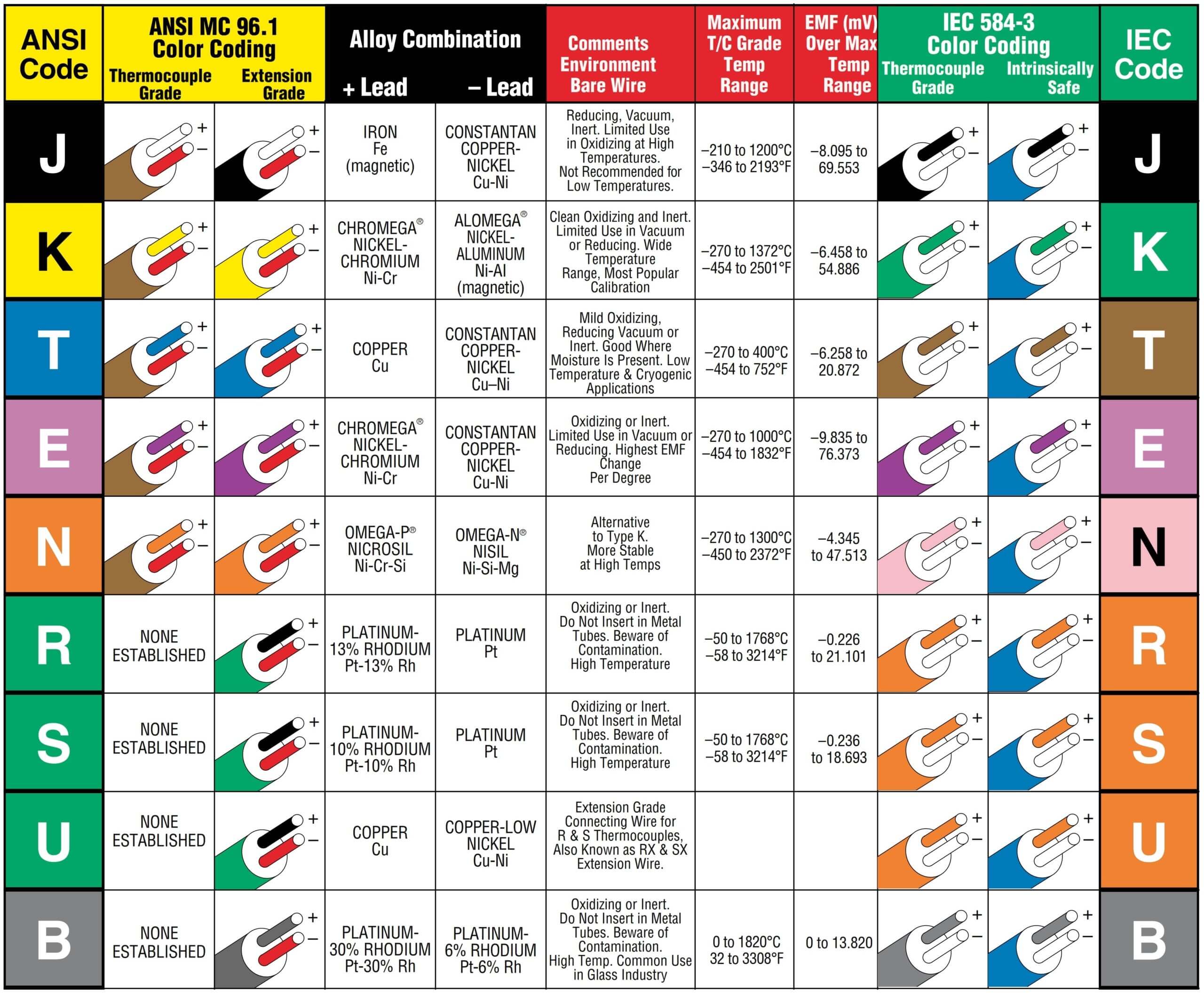
Thermocouple Color Codes

Thermocouple Color Code as per IEC and ANSI Standards

Image Courtesy: Omega

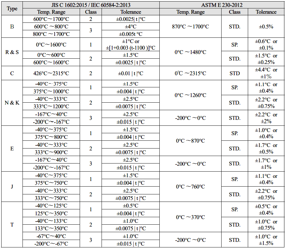
Thermocouple Tolerance

1) Tolerance is referred to as the maximum allowable deviation between hot junction temperature and the temperature derived from the EMF table.

2) ASTM temperature is C or % value for the measured temperature, which is greater.

3) | t | is the measuring temperature indicated by the temperature irrelevant to the symbol + or -.

4) Class 1, 2, or 3 conforms to the old JIS Class 0.4, 0.75 or 1.5, respectively.

5) JIS Standard is identical with IEC, BS or DIN Standard except for a part.

6) The tolerance of JISC1605 and JISC1602 is completely the same.

7) ASTM Standard is same as the old ANSI Standard.

8) Tolerances given in this table apply only to new wire as delivered to the user and do not allow for changes in characteristics with use. (ASTM E230)

9) The standard tolerances shown do not apply to Type E mineral-insulated, metal-sheathed (MIMS) thermocouples and thermocouple cables as described in Specifications E608/E608M and E585/E585M. The standard tolerances for MIMS Type E constructions are the greater of 2.2°C or 0.75 % from 0 to 870°C and the greater of 2.2°C or 2 % from -200 to 0°C.

Thermocouple Tolerance

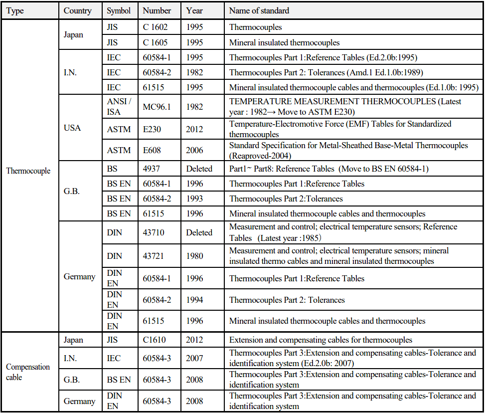
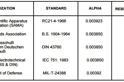
Thermocouple Standard

Thermocouple Standard

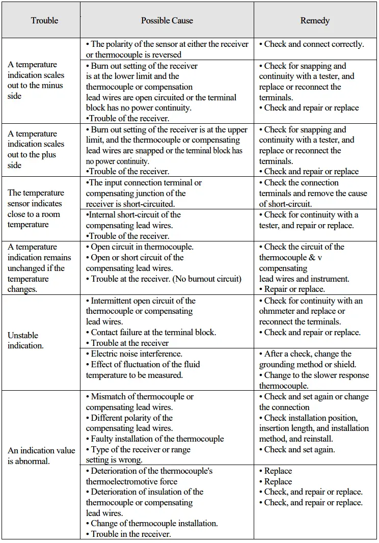
Thermocouple Troubleshooting

Troubleshooting for Thermocouples

Reference: okazaki

Author: Mohammed Khaleel

Read Next:

  • RTD Construction
  • RTD Temperature Error
  • Thermocouple Applications
  • Thermocouple Construction
  • Terminate the Cable Shield
Don't Miss Our Updates
Be the first to get exclusive content straight to your email.
We promise not to spam you. You can unsubscribe at any time.
Invalid email address
You've successfully subscribed !

Continue Reading

Why we use Wheatstone bridge in RTD?
Basics of Thermocouples and RTD
Thermocouple Calibration
How to calculate the tolerance of a RTD sensor
Difference Between RTD, Thermocouple and Thermistor
Helix Bimetallic Thermometer Principle
Share This Article
Facebook Whatsapp Whatsapp LinkedIn Copy Link
Share
2 Comments
  • R JAGAN MOHAN RAO says:
    September 19, 2020 at 10:17 am

    A very good article, with lot of required information can be found at a place. Inclusion of thermocouple color code chart as per the IEC and ANSI standards may be considered for adding more fragrance to the article.

    Reply
  • Dave Bartran says:
    September 21, 2020 at 2:21 am

    You may find the following site of interest when dealing with thermowells and temperature response times,

    https://www.thermowellsoftware.com

    Reply

Leave a Reply Cancel reply

Your email address will not be published. Required fields are marked *

Stay Connected

128.3kFollowersLike
69.1kFollowersFollow
210kSubscribersSubscribe
38kFollowersFollow

Categories

Explore More

Thermocouples Green Rot Effect
What is Temperature ?
Thermistor Working Principle
Thermocouples Burnout detection
What Temperature are Celsius and Fahrenheit Value Same ?
Difficulties with Thermocouples for Temperature Measurement
Resistance Temperature Detectors (RTD) Sources of Error
How to Select Right Thermocouple & Thermowell ?

Keep Learning

Temperature Calibration Bath

Temperature Calibration Bath Principle

Thermocouple Temperature Ranges

Thermocouple Temperature Range Questions and Answers

RTD Questions & Answers

RTD Questions and Answers

Resistance Temperature Detectors Troubleshooting Tips

Resistance Temperature Detectors Troubleshooting Tips

What to Choose RTD or Thermocouple ?

Thermowell Design Guidelines

Single Position Calibration of Temperature Bath

Single Position Calibration of Temperature Bath

field-mounted thermocouple

Thermocouple Extension Wires

Learn More

Power Electronics Objective Questions

Thyristor Chopper Circuits Objective Questions

Conductive Level Switch Principle

Conductive Level Switch Principle

Functions of Rupture Disc

Why is a Rupture Disc Required? – Functions & Selections

Phase Controlled Half Wave Rectifier RL Load

Power Electronics – Phase Controlled Half Wave Rectifier RL Load

Three Phase To Single Phase Wiring Connections

Single Phase Power Wiring Schemes

How to Program Sequential Outputs in PLC

Timer-Based Sequential PLC Program with One Button

Construction of Megger

What is a Megger? Principle, Advantages, Disadvantages, Applications

Pressure Regulator with Flapper-Nozzle Principle

Pressure Regulator with Flapper-Nozzle Principle

Menu

  • About
  • Privacy Policy
  • Copyright

Quick Links

  • Learn PLC
  • Helping Hand
  • Part Time Job

YouTube Subscribe

Follow US
All rights reserved. Reproduction in whole or in part without written permission is prohibited.
Welcome Back!

Sign in to your account

Username or Email Address
Password

Lost your password?