Inst ToolsInst ToolsInst Tools
  • Courses
  • Videos
  • Q & A
    • Interview
      • Instrumentation
      • Electronics
      • Electrical
      • Practical Questions
    • MCQ
      • Instrumentation MCQ
      • Electrical MCQ
      • Electronics MCQ
      • Control Systems MCQ
      • Analog Electronics MCQ
      • Digital Electronics MCQ
      • Power Electronics MCQ
      • Microprocessor MCQ
      • Multiple Choice Questions
  • EE
    • Electronics
      • Electronics Q & A
      • Electronic Basics
      • Electronic Devices & Circuits
      • Electronics Animation
      • Digital Electronics
    • Electrical
      • Electrical Basics
      • Electrical Q & A
      • Power Electronics
      • Electrical Machines
      • Electrical Animation
      • Power Systems
      • Switchgear & Protection
      • Transmission & Distribution
  • Measure
    • Control Valves
    • Calibration
    • Temperature
    • Pressure
    • Flow
    • Level
    • Analyzers
    • Switches
    • Vibration
    • Solenoid Valve
  • Control
    • PLC Tutorials
    • Control Systems
    • Safety Instrumented System (SIS)
    • Communication
    • Fire & Gas System
  • More
    • Design
    • Tools
    • Animation
    • Basics
    • Formulas
    • Standards
    • TextBooks
    • Common
    • Software
    • Excel Tools
    • Erection & Commissioning
    • Process Fundamentals
    • Videos
    • Books
Search
All rights reserved. Reproduction in whole or in part without written permission is prohibited.
Reading: Basic Principles of Electricity
Share
Notification Show More
Font ResizerAa
Inst ToolsInst Tools
Font ResizerAa
  • Courses
  • PLC Tutorials
  • Control Systems
Search
  • Courses
  • Videos
  • Q & A
    • Interview
    • MCQ
  • EE
    • Electronics
    • Electrical
  • Measure
    • Control Valves
    • Calibration
    • Temperature
    • Pressure
    • Flow
    • Level
    • Analyzers
    • Switches
    • Vibration
    • Solenoid Valve
  • Control
    • PLC Tutorials
    • Control Systems
    • Safety Instrumented System (SIS)
    • Communication
    • Fire & Gas System
  • More
    • Design
    • Tools
    • Animation
    • Basics
    • Formulas
    • Standards
    • TextBooks
    • Common
    • Software
    • Excel Tools
    • Erection & Commissioning
    • Process Fundamentals
    • Videos
    • Books
Follow US
All rights reserved. Reproduction in whole or in part without written permission is prohibited.
Inst Tools > Blog > Electrical Basics > Basic Principles of Electricity

Basic Principles of Electricity

Last updated: May 3, 2017 3:40 pm
Editorial Staff
Electrical Basics Instrumentation Design
No Comments
Share
3 Min Read
SHARE

Basic Principles of Electricity

Electricity

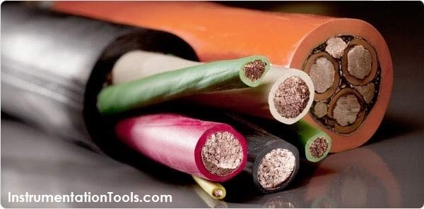
Electricity, simply put, is the flow of electric current along a conductor. This electric current takes the form of free electrons that transfer from one atom to the next. Thus, the more free electrons a material has, the better it conducts. There are three primary electrical parameters: the volt, the ampere and the ohm.

1. The Volt

The pressure that is put on free electrons that causes them to flow is known as electromotive force (EMF). The volt is the unit of pressure, i.e., the volt is the amount of electromotive force required to push a current of one ampere through a conductor with a resistance of one ohm.

2. The Ampere

The ampere defines the flow rate of electric current. For instance, when one coulomb (or 6 x 10¹⁸ electrons) flows past a given point on a conductor in one second, it is defined as a current of one ampere.

3. The Ohm

The ohm is the unit of resistance in a conductor. Three things determine the amount of resistance in a conductor: its size, its material, e.g., copper or aluminum, and its temperature. A conductor’s resistance increases as its length increases or diameter decreases. The more conductive the materials used, the lower the conductor resistance becomes. Conversely, a rise in temperature will generally increase resistance in a conductor.

Ohm’s Law

Ohm’s Law defines the correlation between electric current (I), voltage (V), and resistance (R) in a conductor.

Ohm’s Law can be expressed as: V = I × R

Where: V = volts, I = amps, R = ohms

Ampacity

Ampacity is the amount of current a conductor can handle before its temperature exceeds accepted limits. These limits are given in the National Electrical Code (NEC), the Canadian Electrical Code and in other engineering documents such as those published by the Insulated Cable Engineers Association (ICEA). It is important to know that many external factors affect the ampacity of an electrical conductor and these factors should be taken into consideration before selecting the conductor size.
Don't Miss Our Updates
Be the first to get exclusive content straight to your email.
We promise not to spam you. You can unsubscribe at any time.
Invalid email address
You've successfully subscribed !

Continue Reading

Difference Between Open Circuit and Close Circuit
All About Vortex Flow Meters
Industrial Automation Pre-Engineering Design Documents – Project & Process
Basic Terms used in SIL Verification
What is Static Pressure Limit in DP Transmitter ?
Major issues for Sensors Selection
Share This Article
Facebook Whatsapp Whatsapp LinkedIn Copy Link
Share
Leave a Comment

Leave a Reply Cancel reply

Your email address will not be published. Required fields are marked *

Stay Connected

128.3kFollowersLike
69.1kFollowersFollow
208kSubscribersSubscribe
38kFollowersFollow

Categories

Explore More

Safety Roles & Responsibilities of Process Engineering (Detail Design)
What is a Damper? Types of Dampers in HVAC
How to Solve Cable Tray Sagging ?
Difference between Servo Motor and DC Motor
How to Avoid Process Downtime ?
Interface Level Measurement Selection Guide
Multiple Thermowell Installations Problems
Basics of Thermistors, Thermocouples and RTD’s
Pressure Sensor Specifications
PLC Panel and MCC Panel Interface Signals

Keep Learning

Control Loop

What is a Control Loop ?

Industrial Star Delta Starter for 3-Phase Induction Motor

Star Delta Starter – Working, Circuit, Advantages, Disadvantages

Turbine-Compressor System Architecture

Turbine-Compressor System Architecture

Relay Motor Logic Circuit

Motor Control Circuits

Effects of Long Distance Cables on VFD

Effects of Long Distance Cables between VFD and Motor

Gas Detectors Location Installation

Gas Detectors Installation Techniques

Design Engineering of Process Plant Project

Process Engineering Roles & Responsibilities – Design Company

Why Do We Need to Connect Transformers in Parallel

Why Do We Need to Connect Transformers in Parallel?

Discover More

Solenoid Operated Valves and Latching Valves

Solenoid Operated Valves and Latching Valves

Modbus ASCII and RTU Message Frame

Background of Modbus – ASCII and RTU Data Frames

OB and FB Blocks in Siemens PLC

Procedure for Siemens S7-300 Download from PC to PLC

Digital Electronics Multiple Choice Questions

Memory Devices Objective Questions – Part 3

Power System Protection and Relays Questions & Answers

Power System Protection and Relays Questions & Answers

Siemens PCS 7

What is PCS 7?

Synchronous Generator Salient Pole vs Non Salient Pole

PLC Training Course

#17 PLC Best Practices – Log PLC Uptime and Trend it on HMI

Follow US
All rights reserved. Reproduction in whole or in part without written permission is prohibited.
Welcome Back!

Sign in to your account

Username or Email Address
Password

Lost your password?